Spark plug with increased durability and carbon fouling resistance

Active Publication Date: 2006-03-16
DENSO CORP
View PDF10 Cites 16 Cited by
  • Summary
  • Abstract
  • Description
  • Claims
  • Application Information

AI Technical Summary

Benefits of technology

[0021] The main spark gap has a length X. The auxiliary spark gap has a length Y. The lengths X and Y meet a relation of X>Y. This facilitates ease of discharge of sparks in the auxiliary spark gap when the engine is smoldering.
[0022] The lengths X and Y preferably meet relations of X≦0.9 mm and 0.3 mm≦Y≦X−0.1 mm. This results in a decrease in voltage of electrical discharge in the main spark gap to enhance the voltage endurance of the porcelain insulator and the carbon fouling resistance of the spark plug.
[0023] A minimum distance D between a top end surface of the center electrode and the top end surface of the auxiliary ground electrode meets a relation of D>T+Y. This avoids sparks traveling between the center electrode and the auxiliary ground electrode without passing along the surface of the porcelain insulator to ensure the burning off of carbon deposits on the porcelain insulator by sparks generated in the auxiliary spark gap when the engine is smoldering.
[0024] The inner side surface of the auxiliary ground electrode has an area which defines the auxiliary spark gap between itself and the insulator nose of the porcelain insulator. A distance A between the top end of the metal shell and a top end of the center electrode along an axial direction of the spark plug and a distance C between the top end of the metal shell and a center of the area of the inner side surface of the auxiliary ground electrode in the axial direction of the spark plug have a relation of A−C≦3 mm. This enhances the ignition of an air-fuel mixture in the engine by sparks generated in the auxiliary spark gap. Usually, the deeper the auxiliary spark gap are located in the combustion chamber of the engine, the better the ignition of the mi

Problems solved by technology

When the combustion temperature is extremely low in the engine, so that the temperature of the surface of the porcelain insulator 92 is hardly increased, it may cause the engine to smolder, so that a layer of carbon is deposited on the porcelain insulator 92, thereby resulting in a drop in insulation resistance between the center electrode 93 and the metal shell 94, which, in the worst case, leads to misfiring of the engine.
This caus

Method used


Image

  • Spark plug with increased durability and carbon fouling resistance
  • Spark plug with increased durability and carbon fouling resistance
  • Spark plug with increased durability and carbon fouling resistance

Examples


first embodiment

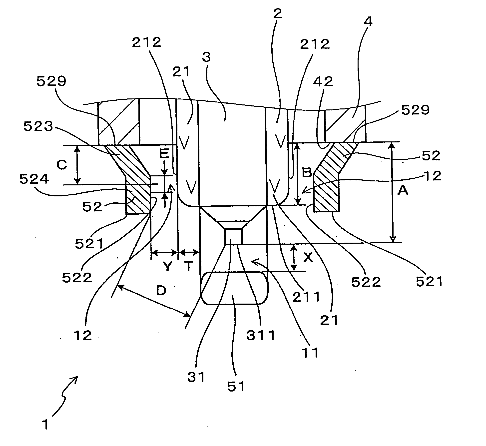
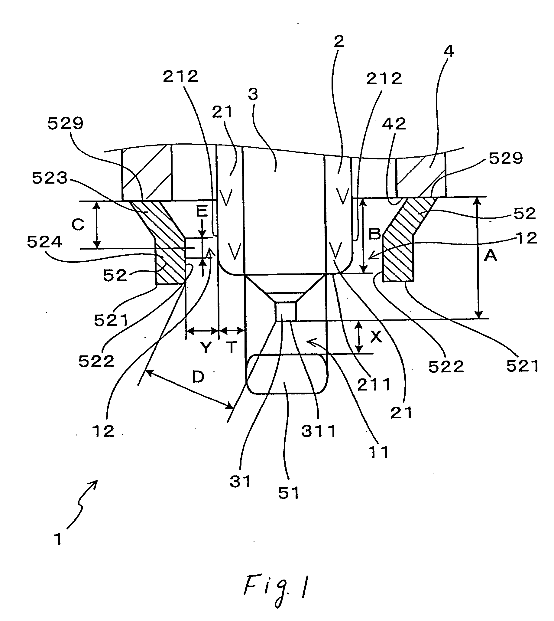
[0041] Referring to the drawings, wherein like reference numbers refer to like parts in several views, particularly to FIGS. 1 and 2, there is shown a spark plug 1 for use in internal combustion engines according to the invention.

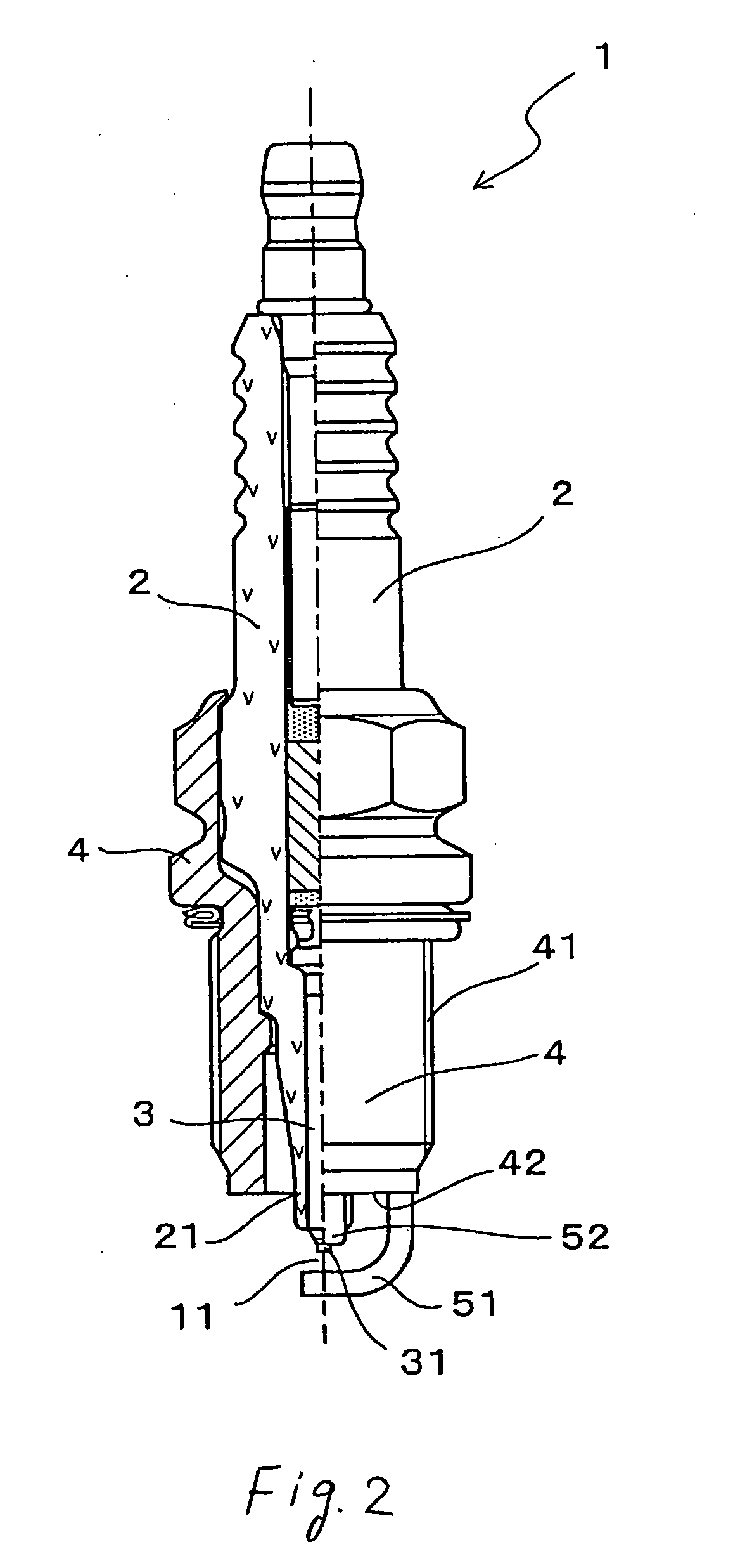
[0042] The spark plug 1, as can be seen from FIG. 2, includes a hollow cylindrical metal shell 4, a porcelain insulator 2, and a center electrode 3. The metal shell 4 has formed on an outer periphery thereof a plug-installation thread 41 for installation of the spark plug 1 in the internal combustion engine. The porcelain insulator 2 is retained in the metal shell 4 and has a nose 21 projecting therefrom. The center electrode 3 is retained in the porcelain insulator 2 and has a tip 31 exposed outside the nose 21 of the porcelain insulator 2. The spark plug 1 also includes a main ground electrode 51 and auxiliary ground electrodes 52. The main ground electrode 51 is welded to the metal shell 4 and faces the tip 31 of the center electrode 3 to define a main s...

second embodiment

[0063]FIG. 3 shows the spark plug 1 for internal combustion engines according to the invention in which each of the auxiliary spark gaps 12 is defined by a curved top corner 213 of the porcelain insulator 2 and the inner side wall 522 of one of the auxiliary ground electrodes 52.

[0064] Each of the auxiliary ground electrodes 52 is made up of a parallel section 525 and a slant section 526. The parallel section 525 extends from the top end 42 of the metal shell 4 in parallel to the outer side wall 212 of the insulator nose 21. The slant section 526 continues from the parallel section 525 and is oriented diagonally inwardly toward the center electrode 3. The slant sections 526 form the auxiliary spark gaps 12 between themselves and the top corner 213 of the porcelain insulator 2. Other arrangements are identical with those in the first embodiment, and explanation thereof in detail will be omitted here.

[0065] The structure of the spark plug 1 of this embodiment enables the auxiliary sp...

third embodiment

[0066]FIG. 4 shows the spark plug 1 for internal combustion engines according to the invention in which noble metal chips 35 and 55 are welded to the center electrode 3 and the main ground electrode 51 to define the main spark gap 11.

[0067] The noble metal chip 35 joined to the center electrode 3 has a transverse sectional area of 0.07 mm2 to 0.64 mm2 in a direction perpendicular to an axis thereof (i.e., the longitudinal center line of the center electrode 3) and a height h1 of 0.3 mm to 1.5 mm in an axial direction thereof (i.e., the lengthwise direction of the center electrode 3). The noble metal chip 55 joined to the main ground electrode 51 has a transverse sectional area of 0.12 mm2 to 0.80 mm2 in a direction perpendicular to an axis thereof and a height h2 of 0.3 mm to 1.5 mm in an axial direction thereof.

[0068] The noble metal chip 35 defines the tip end 311 of the center electrode 3. The main spark gap 11 is formed between the noble metal chips 35 and 55 and has the distan...


PUM


Abstract

A spark plug for an internal combustion engine is provided which includes a metal shell, a porcelain insulator, a center electrode, a main ground electrode, and auxiliary ground electrodes. Each of the auxiliary ground electrodes has an inner side surface facing the center electrode through the porcelain insulator to define an auxiliary spark gap between itself and a nose of the porcelain insulator so as to occupy a minimum distance between the porcelain insulator and the auxiliary ground electrode. This avoids a great local increase in electrical field strength on the auxiliary ground electrode to minimize excessive discharge within the auxiliary spark gap to enhance carbon fouling resistance and durability of the spark plug.

Description

CROSS REFERENCE TO RELATED DOCUMENT [0001] The present application claims the benefit of Japanese Patent Application No. 2004-267098 filed on Sep. 14, 2004, the disclosure of which are totally incorporated herein by reference. BACKGROUND OF THE INVENTION [0002] 1. Technical Field of the Invention [0003] The present invention relates generally to a spark plug with increased durability and carbon fouling resistance for internal combustion engines which may be used in automotive vehicles, co-generation systems, or gas feed pumps. [0004] 2. Background Art [0005] Japanese Patent No. 3140006 (U.S. Pat. No. 6,229,253 B1) teaches a multi-ground electrode spark plug for internal combustion engines. FIG. 12 shows a multi-ground electrode spark plug 9 of the same type. [0006] The spark plug 9 includes a porcelain insulator 92, a center electrode 93 retained within the porcelain insulator 92, a metal shell 94 in which the porcelain insulator 92 is retained with an insulator head 921 exposed out...

Claims


Application Information

Patent Timeline
IPC IPC(8): H01T13/20
CPCH01T13/32H01T13/20
Inventor KOYAMA, TAIJIKANAO, KEIJI
Owner DENSO CORP
Why Eureka
Try Eureka