Wave rotor apparatus

a rotor and wave technology, applied in the direction of mechanical equipment, machines/engines, wave producing pumps, etc., can solve the problems of reducing the sensitivity of axial wave rotors to engine speed changes, and achieves improved efficiency, small frontal area, and high power density.

Active Publication Date: 2009-07-07
BOARD OF TRUSTEES OPERATING MICHIGAN STATE UNIV
View PDF60 Cites 34 Cited by
  • Summary
  • Abstract
  • Description
  • Claims
  • Application Information

AI Technical Summary

Benefits of technology

[0005]The radial wave rotor of the present invention is advantageous over conventional devices since the present invention should produce higher power densities, an improved efficiency, a smaller frontal area, and a smaller size compared to known axial wave rotors. The centrifugal forces of the fluid, created by the present invention, advantageously improve flow scavenging and compression. The offset or generally radial passageways of the wave rotor of the present invention are also easier and less expensive to manufacture as compared to many traditional, axial wave rotors, especially if incorporated into a layered arrangement. The stacked configuration and / or shapes of channels employed in the present invention further provide advantageous variations in cycle timing.
[0006]Moreover, performance of the radial wave rotor of the present invention is simpler to model, predict and analyze in the design stage than traditional wave rotors. Placing turbomachinery in the presently disclosed locations also reduces undesirable pressure losses caused by conventional collectors and / or diffusers. Additionally, the correctional passageways of the present invention advantageously achieve directed and self-actuated aerodynamic control of the internal flow and shock wave pattern. Scavenging processes are also improved by the present invention's use of centrifugal forces. Additional advantages and features of the present invention will become apparent from the following description and appended claims, taken in conjunction with the accompanying drawings.

Problems solved by technology

Traditional attempts to use depressions or pockets to control wave reflections of off-design operation undesirably, reduce the sensitivity of axial wave rotors to engine speed changes.

Method used


Image

  • Wave rotor apparatus
  • Wave rotor apparatus
  • Wave rotor apparatus

Examples


Embodiment Construction

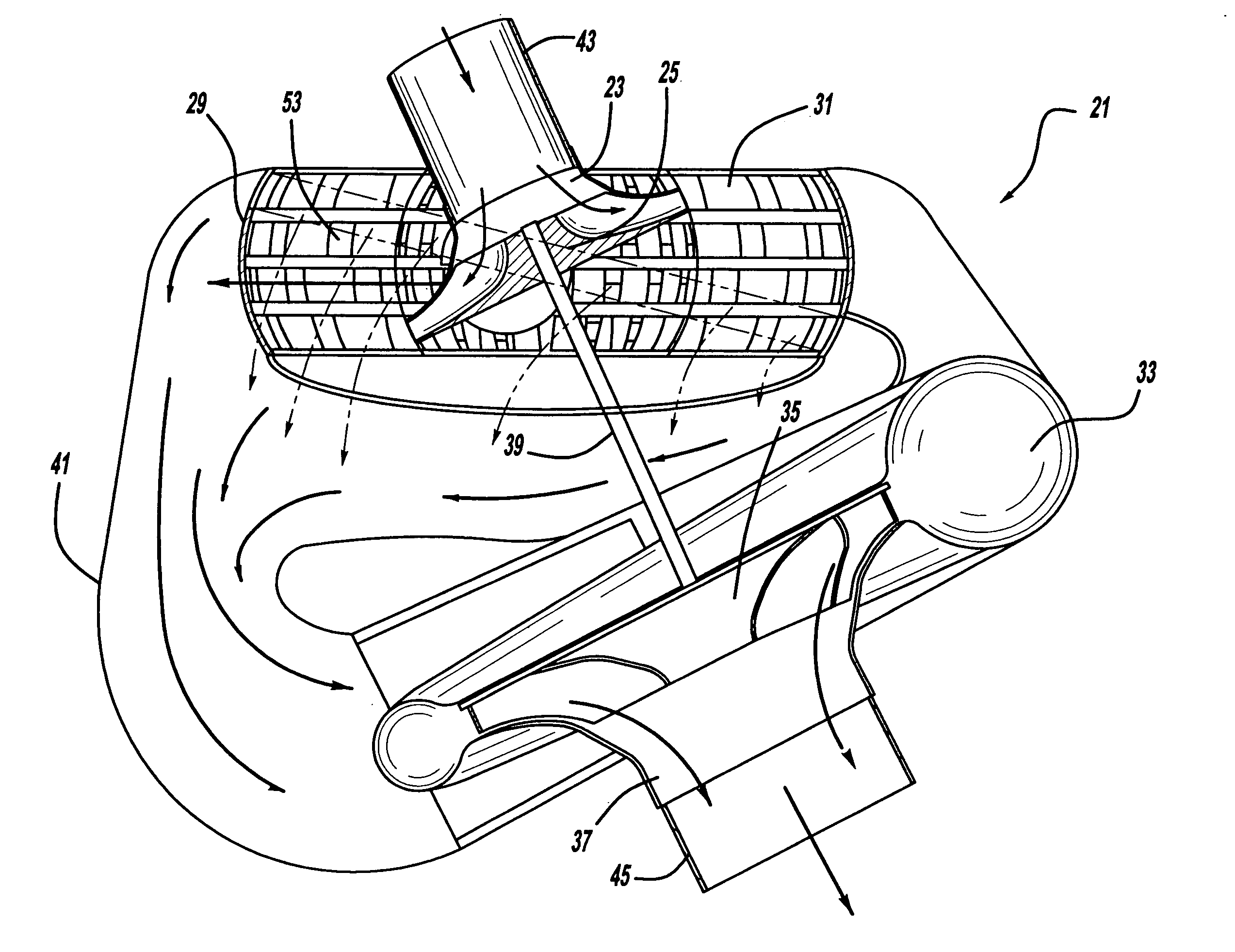
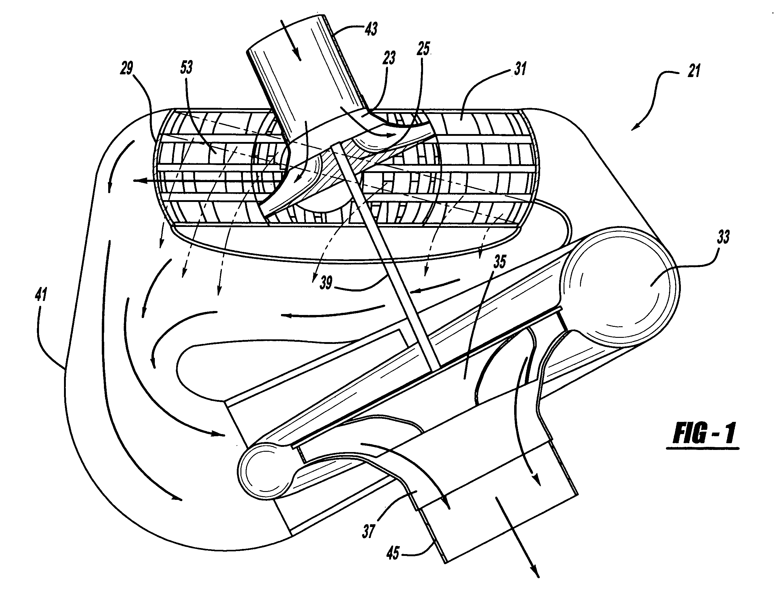
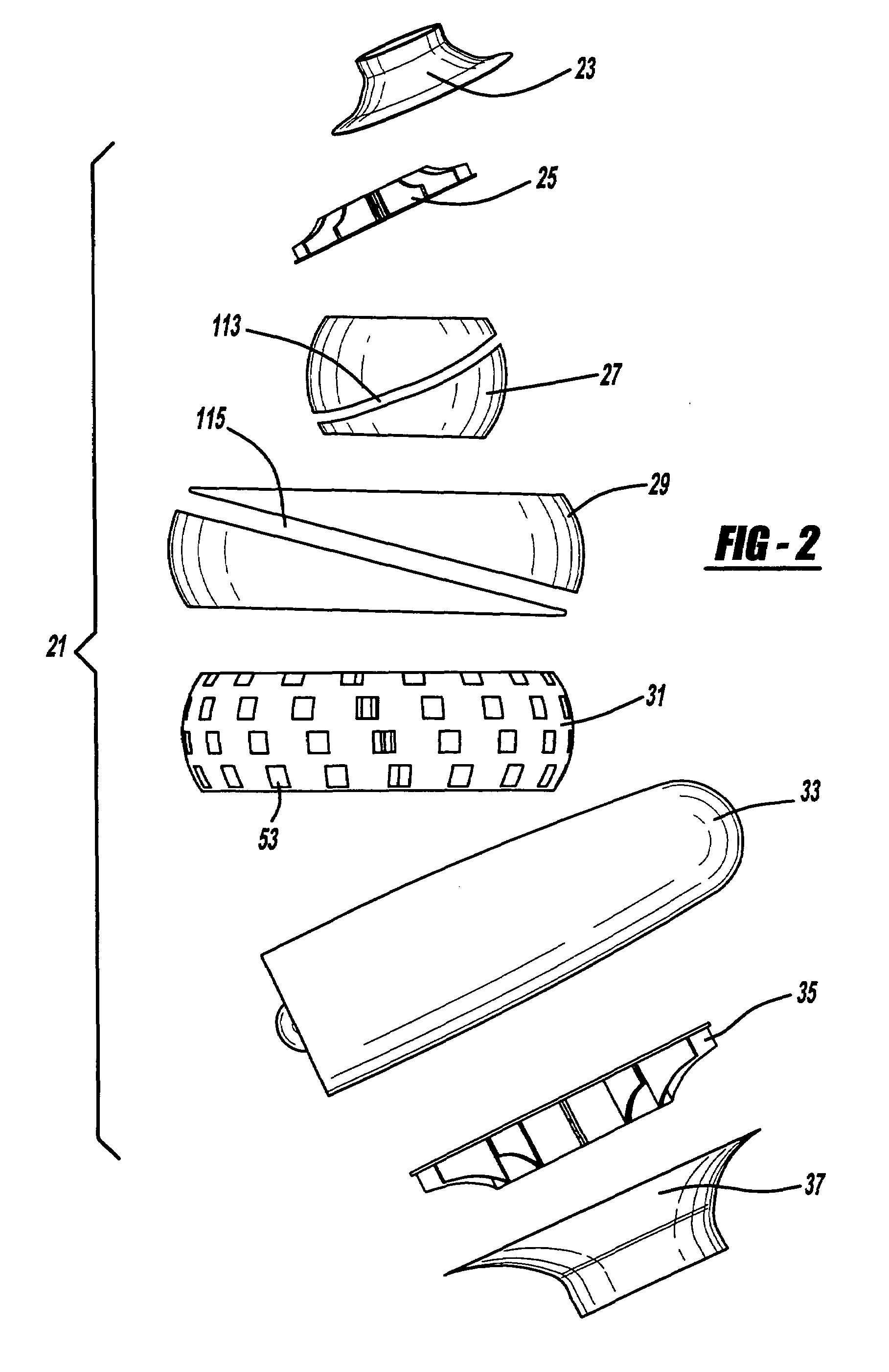
[0032]A wave rotor is a machine in which a fluid is pressurized by generally unsteady shock or compression waves and expanded by expansion waves. As a general principle for wave rotors used in a gas turbine engines, a wave rotor provides a pressure gain additional to that provided by a compressor. It also enables higher combustion end temperatures without raising a turbine inlet temperature since a portion of the energy of the burning gas exiting a combustion chamber is used in the shock compression to increase the pressure and temperature of the fresh air before it enters the combustion chamber. Accordingly, the pre-expanded burned gas is scavenged toward a turbine and channels of the wave rotor are reconnected to the compressor outlet, allowing fresh, pre-compressed air to flow into the wave rotor channels. Thus, wave rotors utilize a high-pressure fluid to transfer its energy directly to a low-pressure fluid when two fluids with different thermodynamic properties are brought into...


PUM


Abstract

A wave rotor apparatus is provided. In another aspect of the present invention, a radial wave rotor includes fluid passageways oriented in a direction offset from its rotational axis. A further aspect of the present invention employs stacked layers of generally radial channels in a wave rotor. Moreover, turbomachinery is located internal to a wave rotor in yet another aspect of the present invention. In yet another aspect of the present invention, a radial wave rotor has an igniter and fuel injector. Correctional passages are employed in still another aspect of the present invention wave rotor.

Description

CROSS REFERENCE TO RELATED APPLICATIONS[0001]This application claims priority to U.S. Provisional patent application Ser. No. 60 / 627,742, filed on Nov. 12, 2004, which is incorporated by reference herein.BACKGROUND OF THE INVENTION[0002]The present invention relates generally to fluid power devices and more particularly to a wave rotor apparatus.[0003]It is known to use an axial wave rotor as a supercharger in internal combustion engines for automotive vehicles. This conventional device is described in P. Akbari and N. Müller, “Gas Dynamic Design Analyses of Charging Zone for Reverse-Flow Pressure Wave Superchargers,” ICES 2003-690, ASME (May 11-14, 2003). Wave rotors have also been proposed for use in propulsive jet engines and power turbines as disclosed in U.S. Pat. No. 6,584,764 entitled “Propulsion Module” which issued to Baker on Jul. 1, 2003; and U.S. Pat. No. 5,894,719 entitled “Method and Apparatus for Cold Gas Reinjection in Through-Flow and Reverse-Flow Wave Rotors” which...

Claims


Application Information

Patent Timeline
Patent Type & Authority Patents(United States)
IPC IPC(8): F02C3/02
CPCF02C3/02F04D35/00F04D25/04F05D2250/314
Inventor MULLER, NORBERTAKBARI, PEZHMANPIECHNA, JANUSZIANCU, FLORIN
Owner BOARD OF TRUSTEES OPERATING MICHIGAN STATE UNIV
Why Eureka
Try Eureka