Closed loop drilling assembly with electronics outside a non-rotating sleeve

a closed loop, drilling assembly technology, applied in the direction of directional drilling, borehole/well accessories, survey, etc., can solve the problems of limiting factors, reduced moment arms available to control drill bits, and overall dimensions of non-rotating sleeves, etc., to prolong the life of drilling assemblies and increase drilling rates

Inactive Publication Date: 2009-07-07
BAKER HUGHES HLDG LLC
View PDF13 Cites 36 Cited by
  • Summary
  • Abstract
  • Description
  • Claims
  • Application Information

AI Technical Summary

Benefits of technology

[0017]In one closed-loop mode of operation, the control unit and BHA processor include instructions relating to the desired well profile or trajectory and / or desired characteristics of a target formation. The control unit maintains overall control over the drilling activity and transmits command instructions to the BHA processor. The BHA processor controls the direction and progress of the BHA in response to data provided by one or more BHA sensors and / or surface sensors, including the orientation sensing system. For example, if sensor azimuth and inclination data indicates that the BHA is straying from the desired well trajectory, then the BHA processor automatically adjusts the force application members of the steering assembly in a manner that steers the BHA to the desired well trajectory. The operation is continually or periodically repeated, thereby providing an automated closed-loop drilling system for drilling oilfield wellbores with enhanced drilling rates and with extended drilling assembly life.

Problems solved by technology

First, a non-rotating sleeve fitted with electronics requires that power and communication lines run across interface between the non-rotating sleeve and bearing assembly.
Increasing the distance between the force application members and the drill bit, however, reduces the moment arm that is available to control the drill bit.
The overall dimensions of the non-rotating sleeve, thus, may be a limiting factor in the configuration of a drilling assembly, and particularly the arrangement of near-bit tooling and equipment.

Method used


Image

  • Closed loop drilling assembly with electronics outside a non-rotating sleeve
  • Closed loop drilling assembly with electronics outside a non-rotating sleeve
  • Closed loop drilling assembly with electronics outside a non-rotating sleeve

Examples


Embodiment Construction

[0027]The present invention relates to devices and methods providing rugged and efficient guidance of a drilling assembly adapted to form a wellbore in a subterranean formation. The present invention is susceptible to embodiments of different forms. There are shown in the drawings, and herein will be described in detail, specific embodiments of the present invention with the understanding that the present disclosure is to be considered an exemplification of the principles of the invention, and is not intended to limit the invention to that illustrated and described herein.

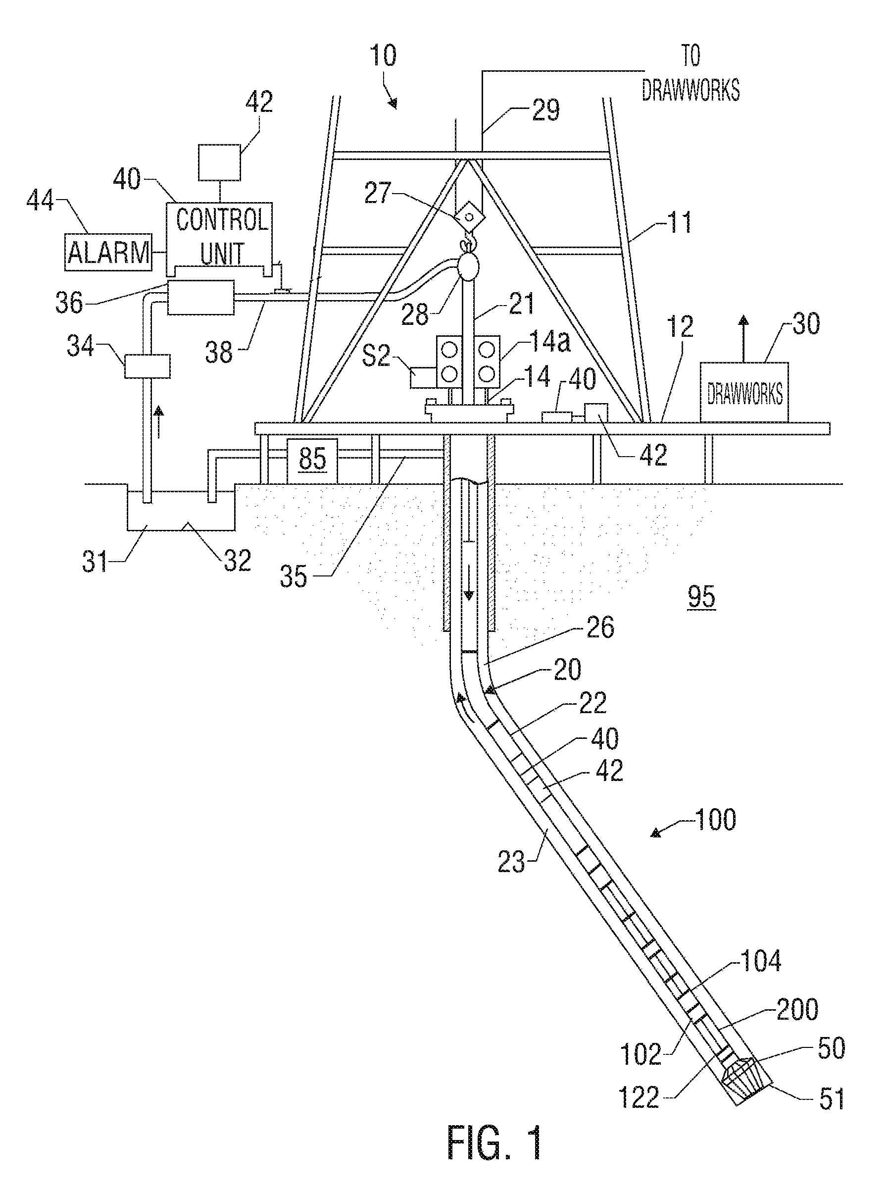
[0028]Referring initially to FIG. 1 there is shown a schematic diagram of a drilling system 10 having a bottom hole assembly (BHA) or drilling assembly 100 shown conveyed in a borehole 26 formed in a formation 95. The drilling system 10 includes a conventional derrick 11 erected on a floor 12 which supports a rotary table 14 that is rotated by a prime mover such as an electric motor (not shown) at a desired rotatio...


PUM


Abstract

A closed-loop drilling system utilizes a bottom hole assembly (“BHA”) having a steering assembly having a rotating member and a non-rotating sleeve disposed thereon. The non-rotating sleeve has a plurality of expandable force application members that engage a borehole wall. An orientation sensing system associated with the rotating member and the non-rotating sleeve provides signals to determine an orientation of the non-rotating sleeve relative to the rotating member. In one embodiment, the orientation sensing system includes a first member positioned in the non-rotating sleeve and a second member positioned in the rotating member. Orientation of the non-rotating sleeve relative to the rotating member is determined from the coaction between the first and second members. The orientation sensing system can use magnetic waves, electrical signals, acoustic signals, radio waves, and / or physical contact.

Description

CROSS REFERENCE TO RELATED APPLICATIONS[0001]This application is a continuation-in-part of U.S. application Ser. No. 10 / 439,155 file May 15, 2003 now U.S. Pat. No. 6,913,095, which takes priority from U.S. Provisional Patent Application No. 60 / 380,646, filed May 15, 2002.BACKGROUND OF THE INVENTION[0002]1. Field of the Invention[0003]This invention relates generally to drilling assemblies that utilize a steering mechanism. More particularly, the present invention relates to downhole drilling assemblies that use a plurality of force application members to guide a drill bit.[0004]2. Description of the Related Art[0005]Valuable hydrocarbon deposits, such as those containing oil and gas, are often found in subterranean formations located thousands of feet below the surface of the Earth. To recover these hydrocarbon deposits, boreholes or wellbores are drilled by rotating a drill bit attached to a drilling assembly (also referred to herein as a “bottom hole assembly” or “BHA”). Such a dr...

Claims


Application Information

Patent Timeline
Patent Type & Authority Patents(United States)
IPC IPC(8): E21B7/06E21B44/00
CPCE21B7/062E21B44/005E21B7/068
Inventor KRUEGER, VOLKER
Owner BAKER HUGHES HLDG LLC
Why Eureka
Try Eureka