
Heterodyne receiver using resonant structures

a receiver and resonance structure technology, applied in the direction of optical radiation measurement, instruments, x/gamma/cosmic radiation measurement, etc., can solve the problems of large scale of such devices, poor efficiency, and not easy to modulate light beams

Active Publication Date: 2009-07-07
ADVANCED PLASMONICS
View PDF306 Cites 7 Cited by
  • Summary
  • Abstract
  • Description
  • Claims
  • Application Information

AI Technical Summary

Benefits of technology

"The patent text describes a method for detecting and decoding encoded electromagnetic signals using micro- and nano-resonant structures. These structures allow for the efficient conversion of electron beam energy into light energy, and can be used to transmit information signals at very high speeds. The patent also describes methods for detecting and decoding the encoded signals using heterodyne mixing techniques and local sources of electromagnetic radiation. The technical effects of this patent include improved methods for detecting and decoding encoded electromagnetic signals, which can be used for high-speed data transmission and in intra-chip or inter-chip communication."

Problems solved by technology

It is not a simple task to modulate a light beam into an electron beam.
But, the scale of such devices is large and their efficiency is poor.

Method used


Image

  • Heterodyne receiver using resonant structures
  • Heterodyne receiver using resonant structures
  • Heterodyne receiver using resonant structures

Examples


Embodiment Construction

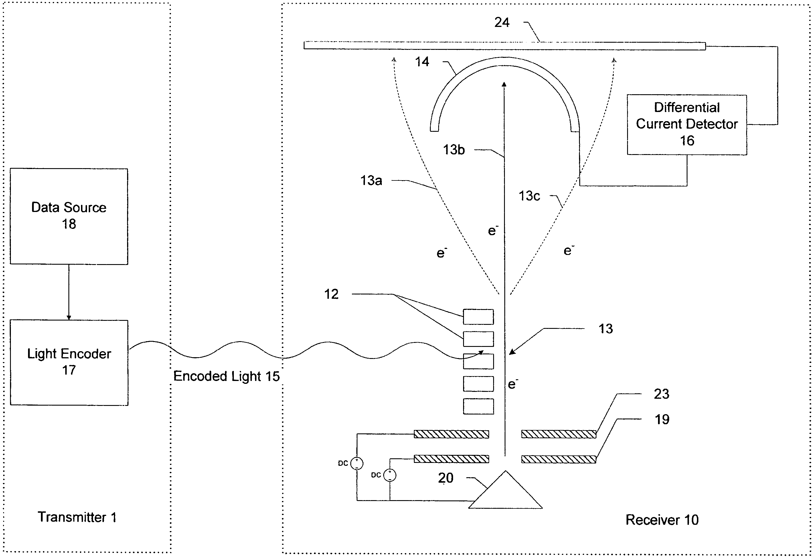
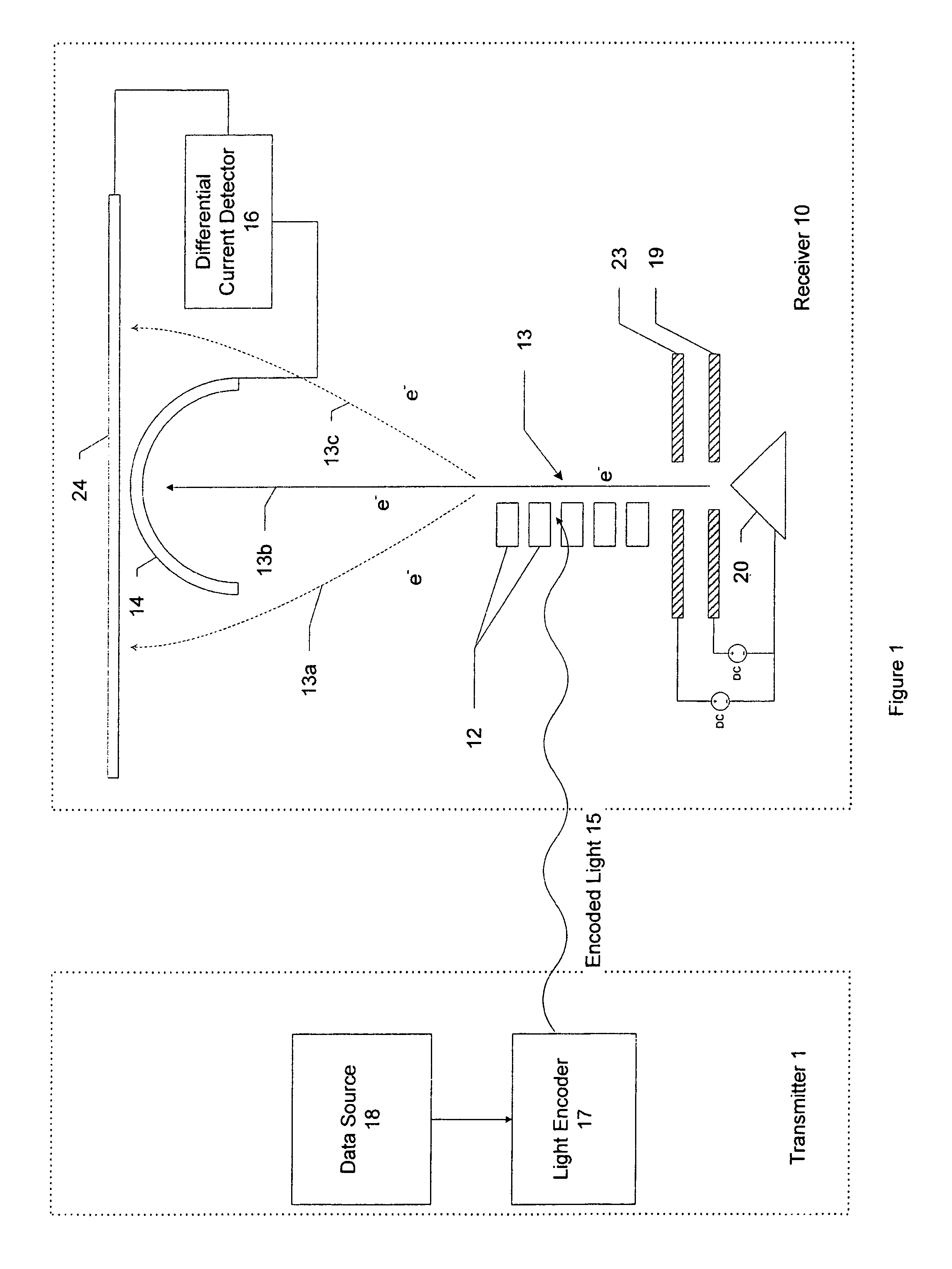
[0046]A transmitter 1 can include an ultra-small resonant structure, such as any one described in U.S. patent application Ser. Nos. 11 / 238,991; 11 / 243,476; 11 / 243,477; 11 / 325,448; 11 / 325,432; 11 / 302,471; 11 / 325,571; 11 / 325,534; 11 / 349,963; and / or 11 / 353,208 (each of which is identified more particularly above). The resonant structures in the transmitter can be manufactured in accordance with any of U.S. application Ser. Nos. 10 / 917,511; 11 / 350,812; or 11 / 203,407 (each of which is identified more particularly above) or in other ways. Their sizes and dimensions can be selected in accordance with the principles described in those applications and, for the sake of brevity, will not be repeated herein. The contents of the applications described above are assumed to be known to the reader.

[0047]Although less advantageous than the ultra-small resonant structures identified in the applications described above, alternatively the transmitter 1 can also comprise any macroscopic or microscopic ...


PUM


Abstract

An electronic receiver for decoding data encoded into electromagnetic radiation (e.g., light) is described. The light is received at an ultra-small resonant structure. The resonant structure generates an electric field in response to the incident light and light received from a local oscillator. An electron beam passing near the resonant structure is altered on at least one characteristic as a result of the electric field. Data is encoded into the light by a characteristic that is seen in the electric field during resonance and therefore in the electron beam as it passes the electric field. Alterations in the electron beam are thus correlated to data values encoded into the light.

Description

COPYRIGHT NOTICE[0001]A portion of the disclosure of this patent document contains material which is subject to copyright or mask work protection. The copyright or mask work owner has no objection to the facsimile reproduction by anyone of the patent document or the patent disclosure, as it appears in the patent and Trademark Office patent file or records, but otherwise reserves all copyright or mask work right whatsoever.CROSS-REFERENCE TO RELATED APPLICATIONS[0002]The present invention is related to the following co-pending U.S. Patent applications which are all commonly owned with the present application, the entire contents of each of which are incorporated herein by reference:[0003]1. U.S. patent application Ser. No. 11 / 238,991, entitled “Ultra-Small Resonating Charged Particle Beam Modulator,” filed Sep. 30, 2005;[0004]2. U.S. patent application Ser. No. 10 / 917,511, entitled “Patterning Thin Metal Film by Dry Reactive Ion Etching,” filed on Aug. 13, 2004;[0005]3. U.S. applicat...

Claims


Application Information

Patent Timeline
Patent Type & Authority Patents(United States)
IPC IPC(8): H03D9/00
CPCH03D9/02H01J25/00
Inventor GORRELL, JONATHANDAVIDSON, MARK
Owner ADVANCED PLASMONICS
Learn More