Coils for electrical machines

Inactive Publication Date: 2009-07-07
ROLLS ROYCE PLC
View PDF3 Cites 1 Cited by
  • Summary
  • Abstract
  • Description
  • Claims
  • Application Information

AI Technical Summary

Benefits of technology

[0013]The substantially undeformable inserts may prevent crushing of the insulating material, e.g. in the region of substantially rigid, conductive lead-outs. Alternatively or additionally the inserts may provide an insulating filler material at turning crossovers (where the turns of a winding having a plurality of concentric cylindrical layers start to come back on themselves) to help reduce or eliminate voids in the compressed coil, particularly at these positions.
[0015]Another aspect of the present invention provides a method comprising the steps of: providing a plurality of conductive wires, each wire being covered in heat-curable electrical insulating material, successively winding the conductive wires around a bobbin to form concentric coil windings, each winding comprising the turns of a respective wire, terminating the start and end turns of each wire in substantially rigid conductive lead-outs, and heating and compressing the coil to cure the insulating material, wherein each lead-out is sized at its connection with the respective wire to substantially prevent a bulge or depression forming radially outwardly of the connection in the cured coil.
[0020]The winding jig of this aspect can carry out the compression of electrically insulating material at non-straight sections of a coil, such as a circular coil. This allows voids in the insulating material at such sections to be reduced or eliminated, so that the voltages which can be carried by the coil can be increased.
[0021]The winding jig of this aspect may also allow the coil to be manufactured such that its final dimensions are precisely defined, thereby allowing the coil to fit in the allocated space in a machine, such as a TFM.
[0027]The coil winding jig may further comprise heating means for heating the coil. In this way the insulating material of the coil can be cured under simultaneous heat and pressure, without the need, for example, for an external heat source.
[0029]All the above aspects of the present invention may allow construction of suitable coils for use in TFMs or other machine types, thereby making these motors practical.

Problems solved by technology

Although this shape is simple geometrically, its manufacture and operation at high voltages require new manufacturing and installation techniques.
The space available for the coil in the overall TFM is generally limited, and therefore the coil dimensions must be tightly controlled.
Together these factors result in an arduous electrical duty and require a coil design which should reduce voltage stress within the coil windings and eliminate corona discharge, factors which could result in premature coil failure in use.
Operation of electrical coils at high voltage and high switching rates such as those encountered when using inverter based drives places significant demands on the coils.
Previous machines have suffered insulation failure as a result of corona discharge and high dV / dt between adjacent windings and between the first and second turns in each winding.

Method used


Image

  • Coils for electrical machines
  • Coils for electrical machines
  • Coils for electrical machines

Examples


Embodiment Construction

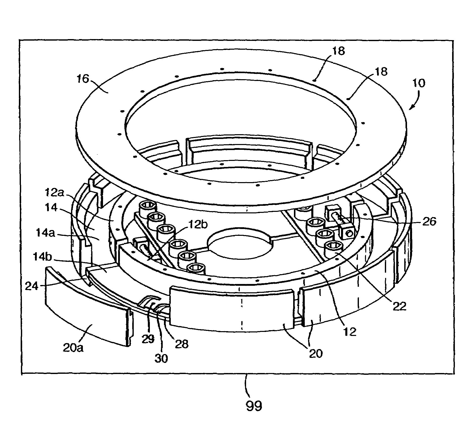
[0037]FIG. 1 shows a winding jig 10 according to an embodiment of the present invention. The jig 10 has a substantially cylindrical bobbin 12 onto which a coil can be wound, the bobbin being connected to a substantially circular or annular lower side plate 14.

[0038]In this description the terms “upper” and “lower” will be used as labels for parts of the jig 10 and coil with reference to the view of FIG. 1. However such terms are not to be considered to limit the jig 10 or a coil to being in those orientations and may be interchanged as appropriate.

[0039]A substantially circular or annular upper side plate 16 forms the second part of the jig 10, and can be attached to the bobbin by bolts through holes 18. The fourth “side” of the jig is provided by a set of circumferentially spaced outer compression segments 20 shown in their attached position, one of these segments (20a) being shown in a removed position.

[0040]The lower side plate 14 and bobbin 12 are divided into two halves 14a and...


PUM

PropertyMeasurementUnit
Dimensionaaaaaaaaaa
Circumferenceaaaaaaaaaa

Abstract

A jig (10) is used to form a coil (50) for an electrical machine. A plurality of conductive wires (56), each covered in a heat-curable electrically insulated material, are wound around a bobbin (12). Each succeeding winding in contra-wound relative to the previous winding, with the first turn (16) of each succeeding winding overlaying the last turn (5) of the previous winding. Undeformable electrically insulated inserts (54) are inserted into the windings before heating and compressing the coil (50) in the jig (10).

Description

TITLE OF THE INVENTION[0001]This is a divisional of National application Ser. No. 11 / 013,967 filed Dec. 17, 2004 now U.S. Pat. No. 7,061,362.FIELD OF THE INVENTION[0002]The present invention relates to the manufacture of coils for electrical machines. It is particularly, but not exclusively, related to: methods of manufacturing coils; apparatuses for manufacturing coils; and the coils themselves.BACKGROUND OF THE INVENTION[0003]In several applications there is a demand for accurately manufactured solenoidal coils, which have high mechanical and electrical integrity.[0004]This demand exists, for example, in transverse flux motors (TFMs), which are permanent magnet machines under development for ship propulsion.[0005]In contrast to the geometrically complex electrical stator windings of conventional motors, a TFM has a simple solenoidal (i.e. substantially circular) coil. Although this shape is simple geometrically, its manufacture and operation at high voltages require new manufactur...

Claims


Application Information

Patent Timeline
IPC IPC(8): H01F27/06H02K15/04
CPCH02K15/0435Y10T29/49071
Inventor MYERS, TIMOTHY M SGILMOUR, KENNETH SHUSBAND, STEPHEN M
Owner ROLLS ROYCE PLC
Why Eureka
Try Eureka