
Apparatus and methods for optically monitoring the fidelity of patterns produced by photolitographic tools

a technology of patterning process and apparatus, applied in the field of apparatus and methods for monitoring the fidelity of patterns produced by patterning process, can solve the problems of reducing yield, faulty device, and inability to individually solve the structure of optical tools, and achieve the effect of reducing yield

Inactive Publication Date: 2009-07-07
KLA TENCOR TECH CORP
View PDF111 Cites 55 Cited by
  • Summary
  • Abstract
  • Description
  • Claims
  • Application Information

AI Technical Summary

Benefits of technology

[0011]In a specific embodiment, the characteristic of the proxy target is an amount of overlay error that is present between two sets of structures of the proxy target image. In a further aspect, the characteristic of the corresponding product feature is a line shortening effect, and it is determined whether the line shortening effect is within a predetermined specification when the overlay error determined for the proxy target is not within a predetermined specification. The predetermined specification of the line shortening effect corresponds to whether the corresponding product feature will likely result in a faulty device that decreases yield. In one embodiment, the proxy target includes a first set of anchor struct

Problems solved by technology

The substructure is not individually resolvable by an optical tool.
The predetermined specification of the line shortening effect corresponds to whether the corresponding product feature will likely result in a faulty device that decreases yield.
Line shortening in any of the periodic lines affects the determined overlay error of the proxy target.

Method used


Image

  • Apparatus and methods for optically monitoring the fidelity of patterns produced by photolitographic tools
  • Apparatus and methods for optically monitoring the fidelity of patterns produced by photolitographic tools
  • Apparatus and methods for optically monitoring the fidelity of patterns produced by photolitographic tools

Examples


first embodiment

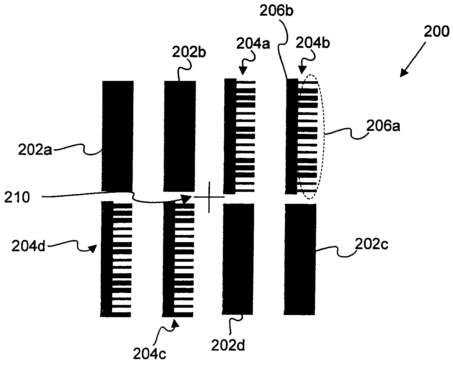
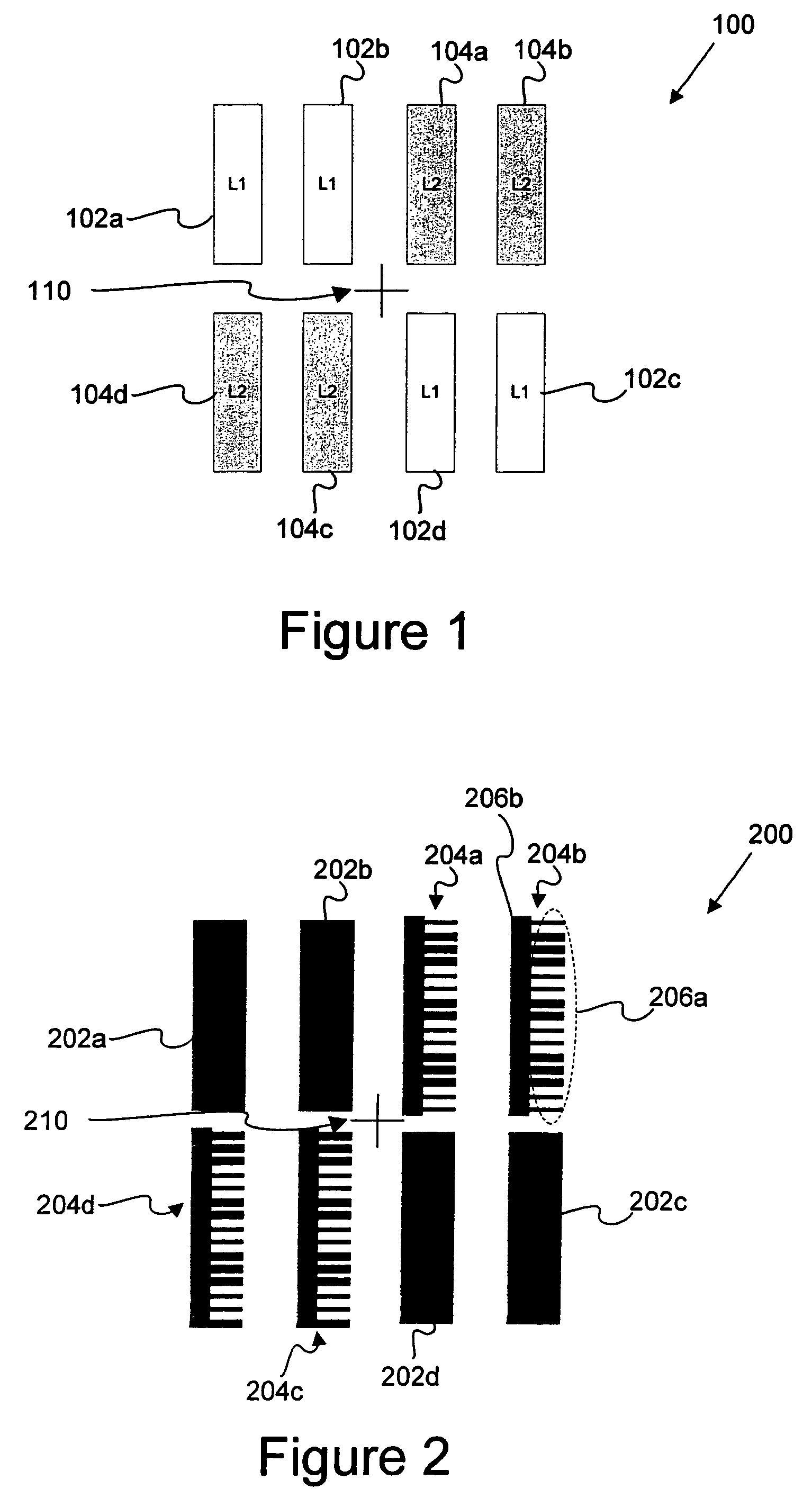
[0031]FIG. 2 is a top view diagrammatic representation of a proxy target 200 for monitoring a line end shortening effect in accordance with the present invention. As shown, the target 200 includes a first set of anchor structures 202a through 202d that are designed to be fairly process robust. That is, these anchor structures 202a-202d have a size and shape (and COS) that remain substantially the same when the process changes. The target also includes a second set of structures 204a-204d that are sensitive to line shortening. The first structures 202a-202d may be printed on a same or different layer than the second set of structures 204a-204d.

[0032]As shown, the second set of structures 204a-204d each include a wide bar 206b coupled with a plurality of smaller substructures 206a. These smaller substructures 206a are not separately resolvable by the optical tool. However, the COS of the overall structures 204a-204d which include these smaller substructures 206a together with the wid...

second embodiment

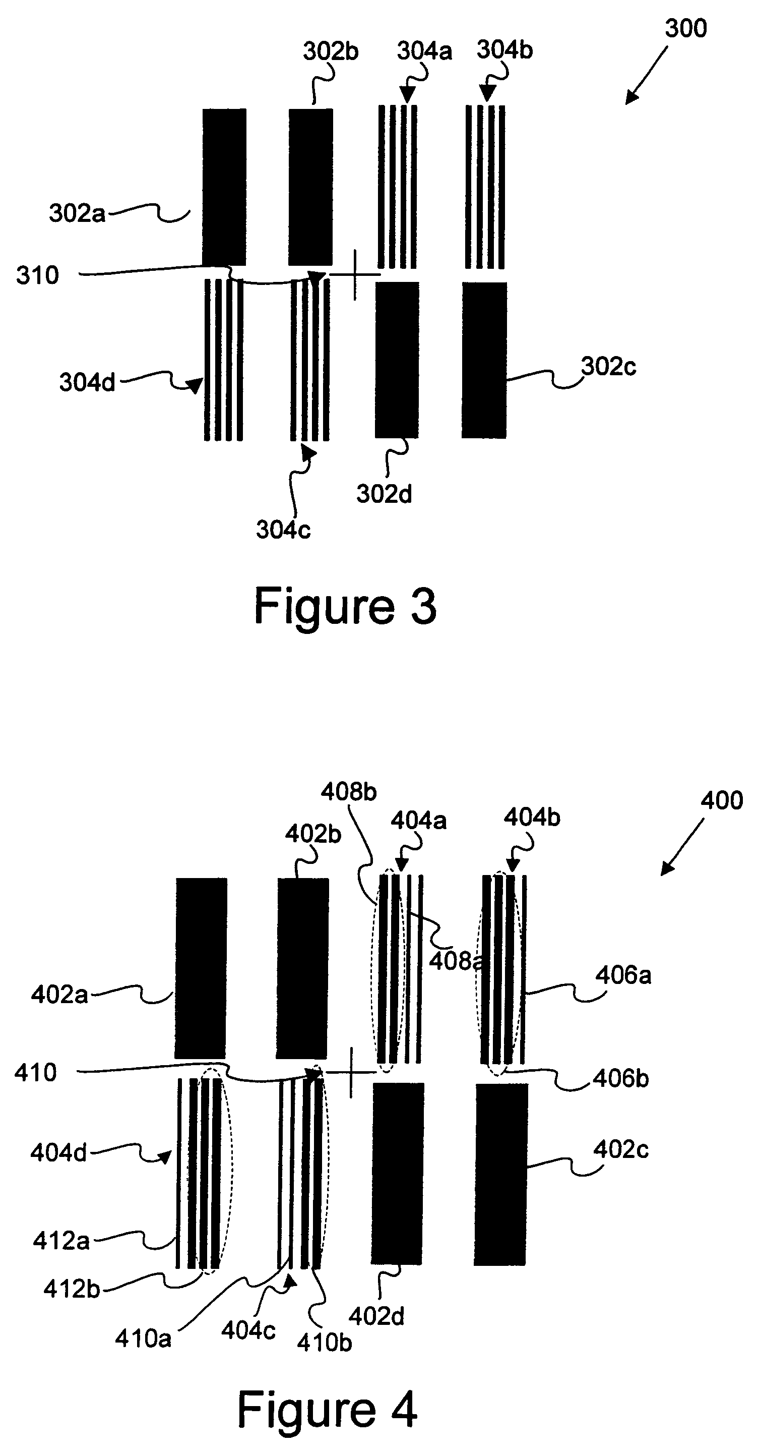
[0037]FIG. 3 is a top view diagrammatic representation of a proxy target 300 for monitoring PPE in accordance with the present invention. In this embodiment, smaller structures 304a˜304d that are not individually resolvable with the optical tool are designed to have a predetermined position relative to a set of larger structures 302a˜302d. For example, the smaller structures 304a˜304d are designed to have a same COM 310 as the larger structures 302a˜302d. The smaller structures 304a˜304d are preferably in a same layer as the larger structures 302a˜302d.

[0038]The smaller structures each correspond to actual product features, e.g., are sized to be as small as design rule features, while the larger structures 302a-302b are process robust type features which are not affected substantially by process changes. However, process changes will tend to shift the set of smaller structures 304a-304d relative to the larger structures 302a-302d. Accordingly, one can monitor the relative offset be...

third embodiment

[0039]FIG. 4 is a top view diagrammatic representation of a proxy target 400 for monitoring a subresolution assist structure (SRAF) characteristic in accordance with the present invention. In general, SRAF structures are present on masks and are designed not to print on the final product wafer. Their purpose is to facilitate the printing of other adjacent features on the mask, e.g., to control the position of adjacent feature edges.

[0040]As shown, the SRAF proxy target 400 includes a first set of process robust features 402a-402d and a second set of SRAF structures 404a-404d. Each set of SRAF structures 404a-404d includes a plurality of printable features and at least one SRAF structure to aid in printing the printable features but are not designed to be printed. As shown, structure 404a includes two medium sized bars 408b and at least one SRAF structure 408a. Similarly, structure 404b includes three medium sized bars 406b and at least one SRAF structure 406a. Structure 404c include...


PUM


Abstract

Disclosed are apparatus and methods for monitoring a characteristic associated with a product feature on a semiconductor product. A proxy target formed from at least one substructure that corresponds to a product feature is provided. The substructure is not individually resolvable by an optical tool. A characteristic of the proxy target is determined based on optically monitoring the proxy target using the optical tool. Based on the determined characteristic of the proxy target, it is then determined whether the corresponding product feature has a characteristic that is within a predetermined specification or whether a process parameter used to fabricate such product feature is within a predetermined specification. In a specific embodiment, the characteristic of the corresponding product feature includes a shape parameter and a position parameter.

Description

CROSS REFERENCE TO RELATED PATENT APPLICATION[0001]This application claims priority of U.S. Provisional Patent Application No. 60 / 643,983 filed 14 Jan. 2005 by Michael E. Adel et al., which application is incorporated herein by reference in its entirety for all purposes.BACKGROUND OF THE INVENTION[0002]This invention pertains to semiconductor patterning processes. More particularly, it pertains to apparatus and methods for monitoring the fidelity of patterns produced by patterning processes, such as photolithography and etching processes that are used to pattern semiconductor materials.[0003]A typical semiconductor product device is formed from a number of product features residing and coupled together within multiple semiconductor layers. Each layer will typically include numerous product features belonging to the same or different product devices. Each layer of product features or pattern is generally formed using some type of semiconductor patterning process, such as photolithogr...

Claims


Application Information

Patent Timeline
IPC IPC(8): G01B11/00G03C5/00G06K9/00
CPCG03F1/14G03F1/44G03F7/70433G03F1/36G06K9/036G06T7/001G03F7/70633G06T2207/30148G03F1/68G06V10/993
Inventor ADEL, MICHAEL E.PREIL, MOSHEMONAHAN, KEVINBEVIS, CHRISTOPHER F.TSAI, BENGHINOVKER, MARK
Owner KLA TENCOR TECH CORP
Learn More