Fluid injector system

a technology of injector system and fluoride, which is applied in the field of fluoride injector system, can solve the problems of difficult calculation of the precise amount of contrast media needed for a particular patient and procedure, under- or over-filling of the syringe chamber, and less than optimal imag

Inactive Publication Date: 2009-07-28
ACIST MEDICAL SYST
View PDF63 Cites 39 Cited by
  • Summary
  • Abstract
  • Description
  • Claims
  • Application Information

AI Technical Summary

Benefits of technology

[0013]A further object of the present invention is to provide

Problems solved by technology

Due to the variability of these parameters, it is often difficult to calculate the precise amount of contrast media needed for a particular patient and procedure.
As a result, there exists the potential that the syringe chamber will be either under-filled or over-filled for a particular patient and/or procedure.
If the chamber is under-filled, an insufficient volume of contrast media will be injected into the patient, resulting in a less than optimal image and requiring that the procedure be repeated.
This is not only expensive due to the high cost of contrast media, but is also potentially harmful to the patient in view of the additional radiation exposure and contrast dose injected into the patient.
Conversely, if the syringe is over-filled, there will be an excess volume of contrast media remaining in the syringe after completion of the imaging procedure.
Although over-filling the syringe avoids the problem of having to repeat the imaging procedure, over-filling wastes contrast medi

Method used


Image

  • Fluid injector system
  • Fluid injector system
  • Fluid injector system

Examples


Embodiment Construction

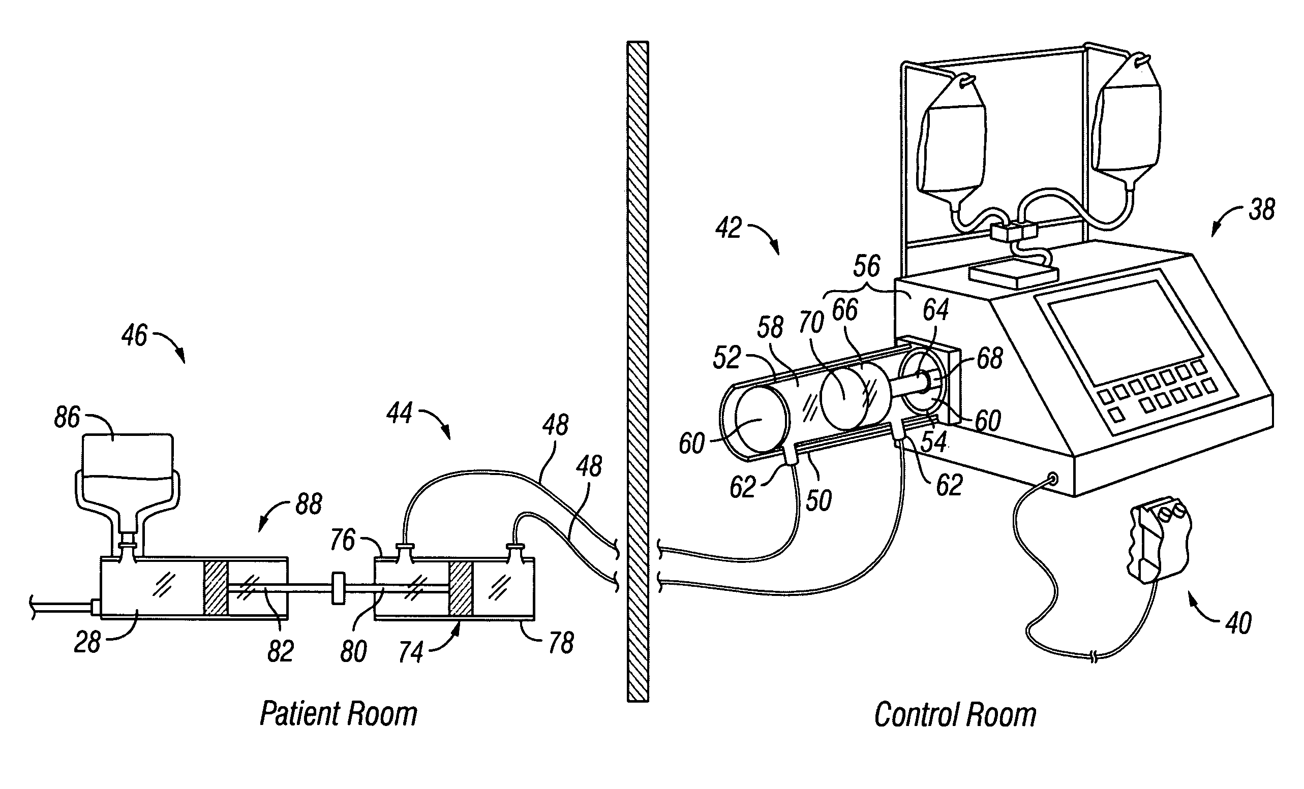
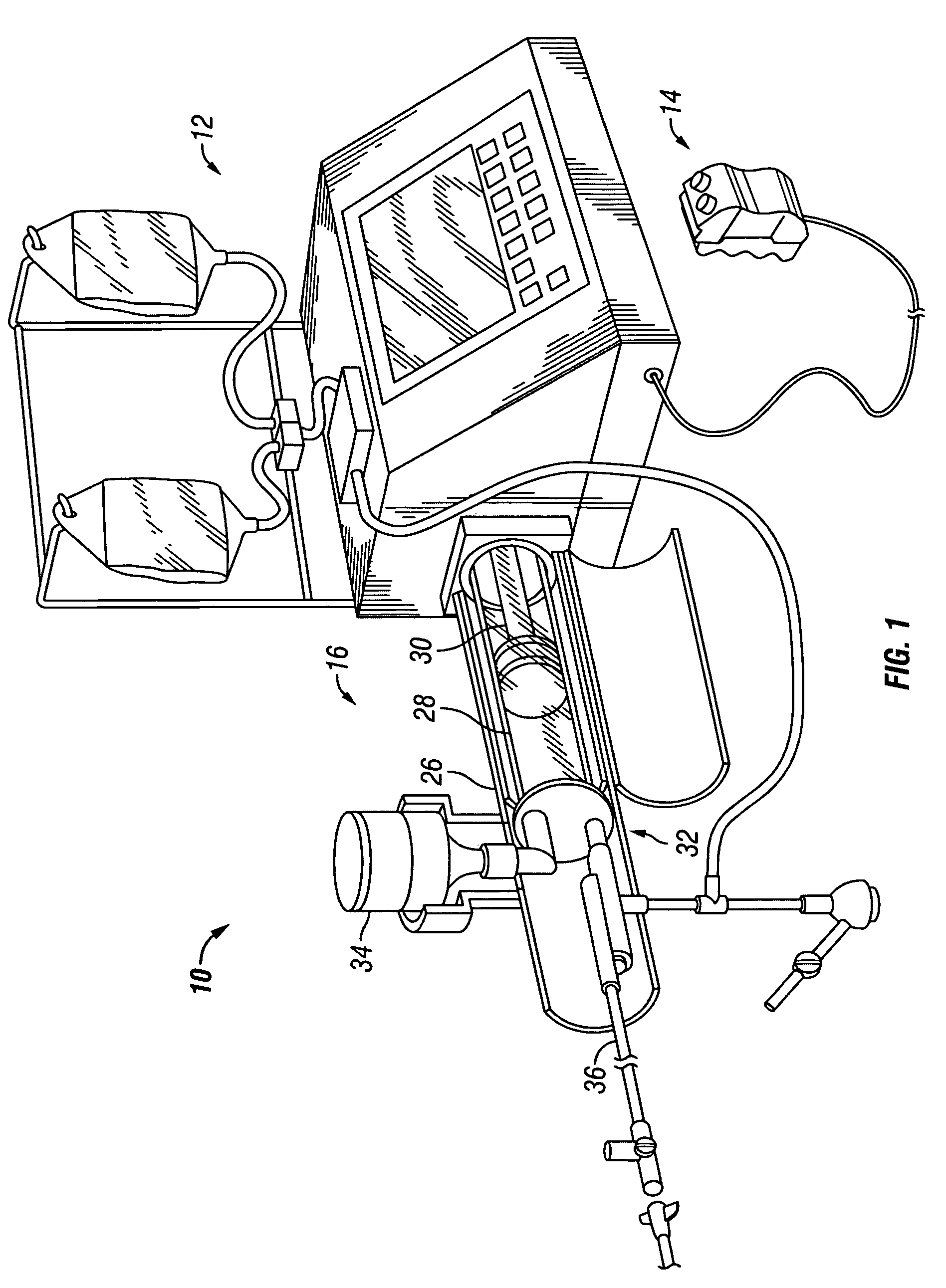
[0037]Referring to FIG. 1, an embodiment of an injector system 10 used to inject fluid into a blood vessel under interactive physician control in accordance with the present invention includes a main console 12, a hand held control 14 and a syringe holder subassembly 16. An example of an injector system 10 included within the scope of the present invention is disclosed in U.S. Pat. No. 6,221,045 to Duchon et al., and is hereby incorporated by reference in its entirety into the present application. It should be noted that the description and figures of the present application are meant to be illustrative only and not limiting. In addition, references to a user interface, user interface / console and similar user control devices are intended to include components similar to the main console and hand-held / remote control, as previously described. Further, the hand-held / remote control may be located in a control room or the same room as the patient and, further, may also be used in the ste...


PUM


Abstract

Fluid injector systems used for a variety of imaging and injection procedures are disclosed. The systems may include separate modules or assemblies that may be located in different rooms of a hospital or imaging facility. Various single use and multiple use components may also be used with the modules or assemblies of the system. In addition, the injector system may include hydraulic and/or pneumatic fluid sources to power the system modules of the present invention.

Description

CROSS REFERENCE TO RELATED APPLICATIONS[0001]The present application claims priority of U.S. Provisional Application Ser. No. 60 / 268,744, filed Feb. 14, 2001, whose contents are fully incorporated herein by reference.BACKGROUND OF THE INVENTION[0002]In many medical environments, a medical fluid is injected into a patient during diagnosis or treatment. One example is the injection of contrast media into a patient to improve computed tomography (CT), angiographic, magnetic resonance (MR) or ultrasound imaging using a powered fluid injection system.[0003]Various manual and automated injection systems used for performing the above-referenced procedures are known in the art. Most current systems include a console and / or control device for controlling the injector. One example of a control device used with an injector system is disclosed in U.S. Pat. No. 5,988,587 to Duchon et al., the disclosure of which is herein incorporated by reference. In addition, a syringe and other disposable com...

Claims


Application Information

Patent Timeline
IPC IPC(8): A61M37/00A61M5/00A61M5/142A61M5/145
CPCA61M5/14216A61M5/14546A61M5/007A61B6/548A61M2005/14513
Inventor DUCHON, DOUGLASGEROLD, JASON
Owner ACIST MEDICAL SYST
Why Eureka
Try Eureka