Compact fan motor and electric device comprising a compact fan motor

a fan motor and electric device technology, applied in the direction of positive displacement liquid engines, liquid fuel engines, pumping pumps, etc., can solve the problems of difficult miniaturization of hall elements and coils, the effective area of the diameter direction of the impeller is likely to be still smaller, etc., to achieve the effect of extending the effective area of the vanes and facilitating further miniaturization

Inactive Publication Date: 2009-07-28
COPAL CO LTD
View PDF17 Cites 21 Cited by
  • Summary
  • Abstract
  • Description
  • Claims
  • Application Information

AI Technical Summary

Benefits of technology

[0010]The compact fan motor has a rotor and a stator accommodated in the tubular case of the motor body and there is no need for providing a magnet on a back side of the impeller, and as a result, it is easier to broaden an effective area in the diameter direction of the vane of the impeller even if the impeller is made smaller. It is also easier to extend the effective area of the vane of the impeller in the direction along the axis of rotation of the shaft because less constraint is imposed on layout on the back side of the impeller. Further, when mounting the motor body to the holder, the motor body is inserted through the motor body insertion opening into the case accommodating portion while positioning the spring terminals so that the spring terminals maintain contact with the pair of conductors. Then, the tubular case is pressed in the direction perpendicular to the axis of rotation of the shaft by an elastic force of the spring terminals so that the tubular case is pushed against the inner wall surface of the case accommodating portion, temporarily holding the motor body to the holder. Since the motor body is temporarily held inside the holder while the spring terminals contacts with the conductors, as described above, assembly of the compact fan motor is made easier and also a stable energized state between the spring terminals and conductors can be maintained more easily. Further, use of known motor bodies makes reduction in the number of components and costs possible.
[0013]With the above structure, the spring terminals and conductors can easily be brought into contact during assembly by inserting the pair of sidewall surfaces of the terminal block along the guide surfaces of the terminal block accommodating portion into the terminal block accommodating portion. Also, when mounting the motor body to the holder, the spring terminals and conductors are less likely to be dislocated and contact failure will not occur. Furthermore, since the terminal block is sandwiched by the pair of guide surfaces of the terminal block accommodating portion, the motor body can be prevented from swinging in the holder, making maintenance of a stable energized state between the spring terminals and conductors still easier.
[0014]It is more suitable if the motor body is fixed inside the holder by pressing the edge on a side of the motor body insertion opening of the holder. By pressing the holder in such a position, the motor body can easily and reliably be fixed to the housing after loading the motor body into the holder, preventing the motor body from falling through the motor body insertion opening. Also, if a metallic tubular case is fixed to a resin holder only by press fitting, for example, the fixed portion is likely to be affected by aging due to different coefficients of thermal expansion resulting from a difference in material. If, however, the motor body is fixed to the holder by pressing, as described above, the fixed portion is less likely to be affected by aging even if the holder and the motor body are made of different materials, contributing to longer life.
[0017]According to the present invention, further miniaturization can be facilitated while extending an effective area of vanes of an impeller.

Problems solved by technology

Particularly, if the impeller is made smaller with miniaturization of the fan motor, the boss portion is hard to miniaturize because of many constraints of the magnet fixed to the impeller in connection with the coil on the circuit board, resulting in the effective area in the diameter direction of the impeller likely to be made still smaller.
Further, the circuit board fixed to the housing must also be made smaller with miniaturization of the fan motor, but miniaturization thereof is hard in consideration of arrangements of the Hall element and coil.

Method used


Image

  • Compact fan motor and electric device comprising a compact fan motor
  • Compact fan motor and electric device comprising a compact fan motor
  • Compact fan motor and electric device comprising a compact fan motor

Examples


Embodiment Construction

[0025]A suitable embodiment of a compact fan motor 1 according to the present invention will be described below in detail with reference to drawings.

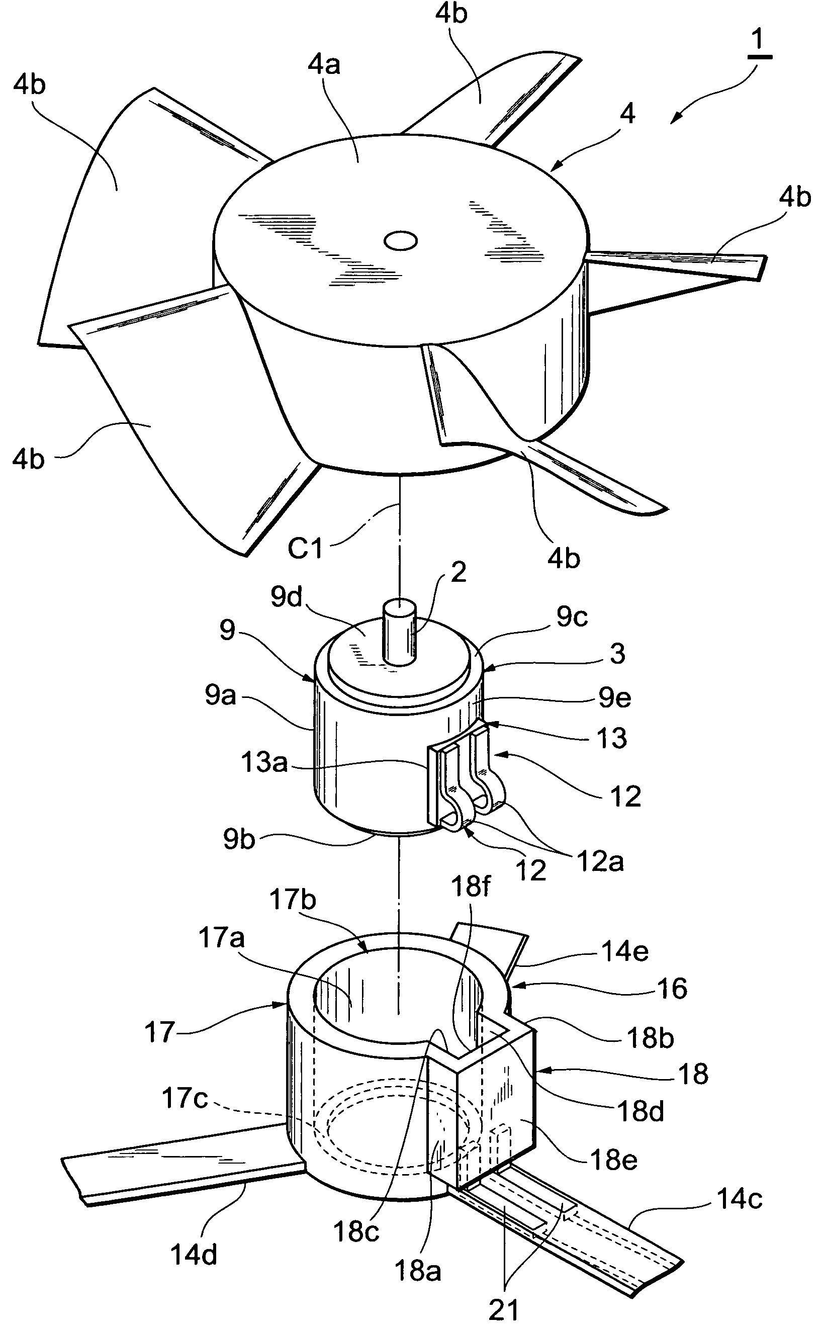
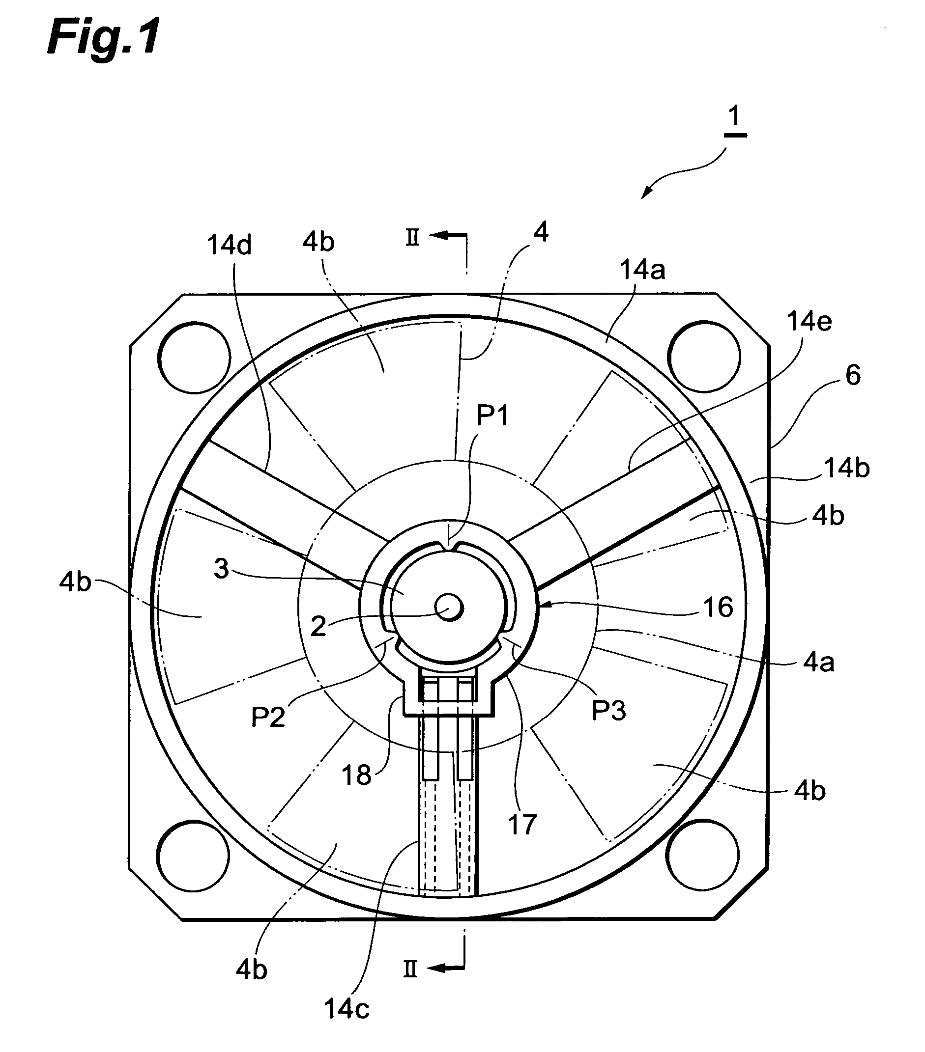
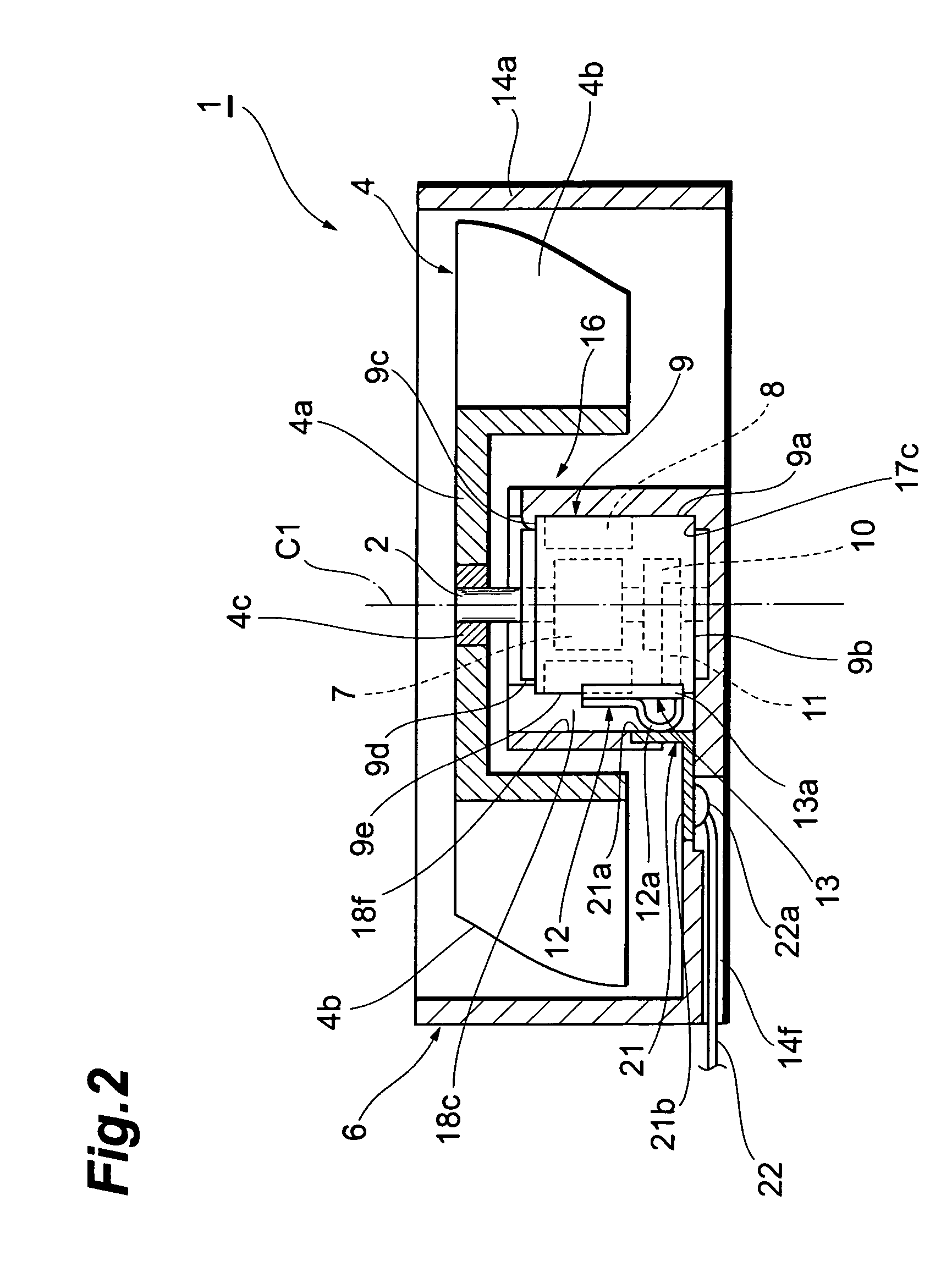
[0026]As shown in FIGS. 1 to 3, the compact fan motor 1 includes a motor body 3 having a rotating shaft 2, an impeller 4 fixed to the shaft 2, and a housing 6 accommodating the motor body 3 and the impeller 4. The compact fan motor 1 is a small axial flow fan motor that sends out air in a direction along an axis of rotation C1 of the shaft 2 by rotation of the impeller 4, and is incorporated in an electronic device such as a mobile phone and a personal computer to cool the device.

[0027]The motor body 3 includes a tubular case 9 for accommodating a rotor 7 and a permanent magnet 8. The tubular case 9 includes a metallic tubular body portion 9a and a bottom bracket 9b, which is fixed to a back end of the body portion 9a by pressing. A step portion 9c is formed at a front end of the body portion 9a by diameter reduction and a neck 9d (fron...


PUM


Abstract

A compact fan motor including a motor body having a tubular case accommodating a rotor, a permanent magnet, and brushes, and a pair of spring terminals that are connected to the brushes, sticks out from a peripheral wall of the tubular case, and has elasticity in a direction perpendicular to an axis of rotation of a shaft; an impeller fixed to the shaft sticking out from a front end of the tubular case; a holder having a case accommodating portion that is provided in a housing accommodating the motor body and impeller and has an inner wall surface extending in the direction of the axis of rotation of the shaft, and a motor body insertion opening provided at an edge of the case accommodating portion; and a pair of conductors provided on the inner wall surface of the holder while contacting with the spring terminals.

Description

BACKGROUND OF THE INVENTION[0001]1. Field of the Invention[0002]The present invention relates to a compact fan motor incorporated in various electronic devices such as mobile phones, car navigation systems, camcorders, and personal computers, and to an electronic device comprising a compact fan motor.[0003]2. Related Background of the Invention[0004]A brushless fan motor is known as a conventional technology in this field. In this type of fan motor, a shaft is supported by a bearing provided in a housing and an impeller is fixed to a front end of the shaft. An annular magnet is fixed to a back side of the impeller. A circuit board is fixed to the housing, and a coil disposed opposite to the magnet and a Hall element for detecting magnetic poles of the magnet are mounted on the circuit board. The impeller rotates in one direction when power distribution to the coil is switched after magnetic pole detection by the Hall element (See Patent Document 1 and Patent Document 2).[0005][Paten...

Claims


Application Information

Patent Timeline
Patent Type & Authority Patents(United States)
IPC IPC(8): H02K5/22F04B17/03F04D25/08
CPCF04D29/624F04D25/0606F04D25/0693H02K5/225H02K5/04H02K7/14
Inventor KASAI, TOSHIAKIHOSHINA, TOMOAKI
Owner COPAL CO LTD
Why Eureka
Try Eureka