Process for identifying the location of a break in a scan chain in real time

a scan chain and break technology, applied in the field of real-time process for identifying the location of a break in a scan chain, can solve the problems of accumulating the number of high failures and low failures for each scan cell

Active Publication Date: 2009-07-28
ADVANTEST CORP
View PDF5 Cites 23 Cited by
  • Summary
  • Abstract
  • Description
  • Claims
  • Application Information

AI Technical Summary

Problems solved by technology

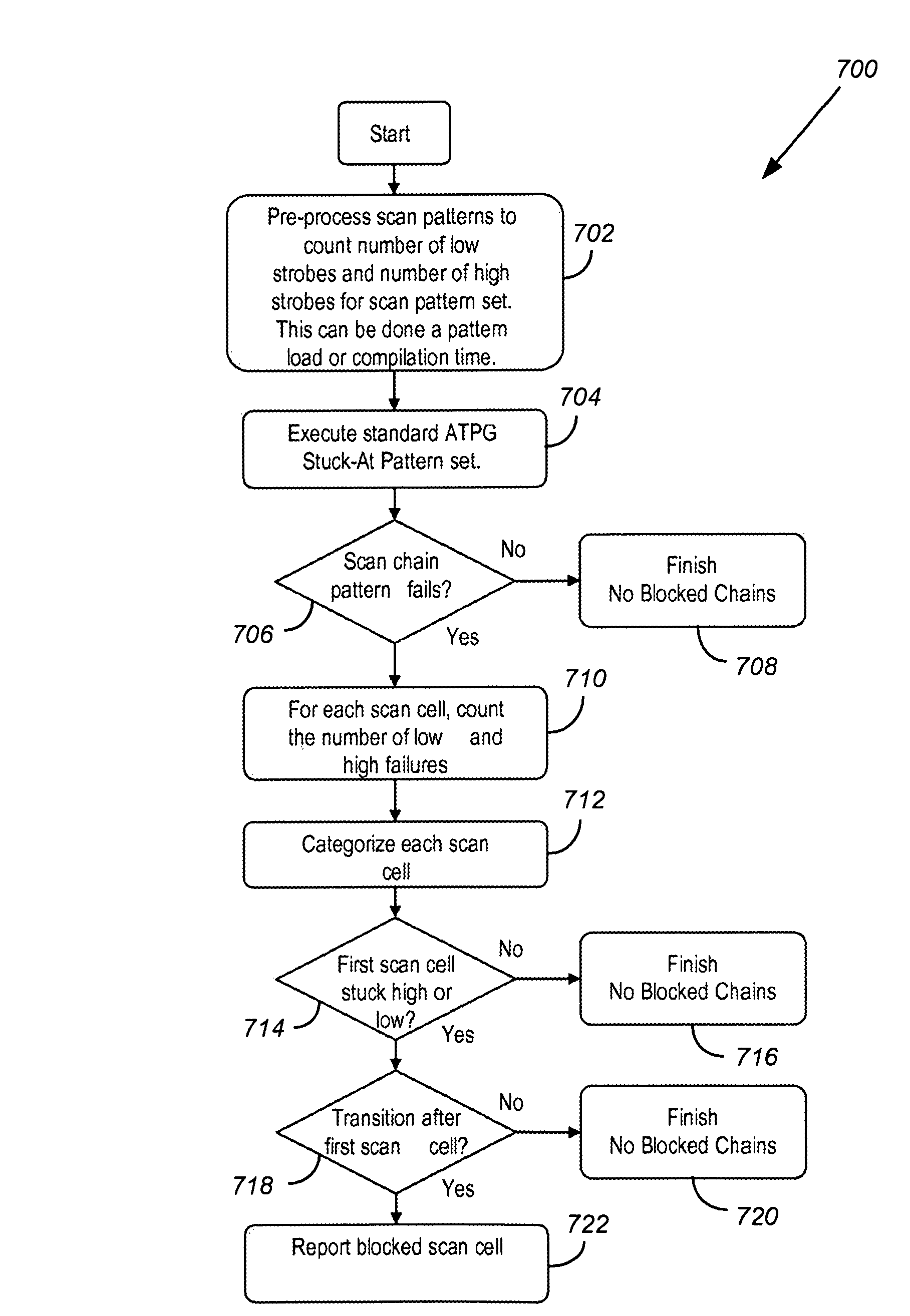
If there are failures, accumulate the number of high failures and low failures for each scan cell.

Method used


Image

  • Process for identifying the location of a break in a scan chain in real time
  • Process for identifying the location of a break in a scan chain in real time
  • Process for identifying the location of a break in a scan chain in real time

Examples


Embodiment Construction

[0040]FIG. 4 shows a timing diagram for a test pattern set with four scan patterns, three scan chains, and four scan cells per each chain to illustrate the multiple dimensions. In this example, 48 total strobes are shown for 12 scan cells. For each scan chain, there is a scan output signal. Each scan cell must be stitched into a scan chain.

[0041]Applications today may include millions of scan cells. These scan cells are distributed amongst a number of scan chains that may range from a handful to hundreds. Thus, scan chains may contain hundreds of scan cells to tens of thousands. For example, if a device contains 1 million scan cells and 100 scan chains, each scan chain would contain about 10,000 scan cells. The exact number of scan cells in each scan chain is determined by the chip designer. However, the designer usually strives to have balanced scan chains for optimum test time performance.

[0042]Regardless of the organization of scan chains, each scan cell is typically strobed per ...


PUM


Abstract

A process for identifying the location of a break in a scan chain in real time as fail data is collected from a tester. Processing a test pattern before applying it on a tester provides a signature enabling a method for a tester to identify a scan cell which is stuck during the time the tester is operating on a device under test rather than accumulating voluminous test data sets for delayed offline analysis.

Description

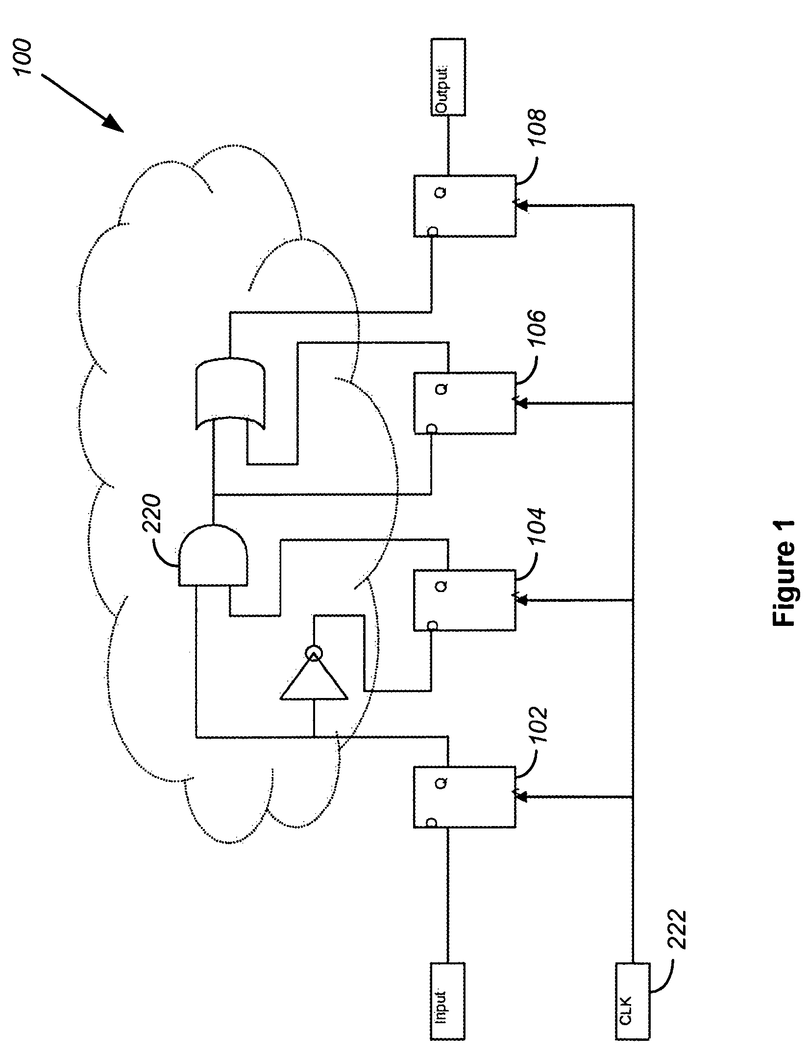
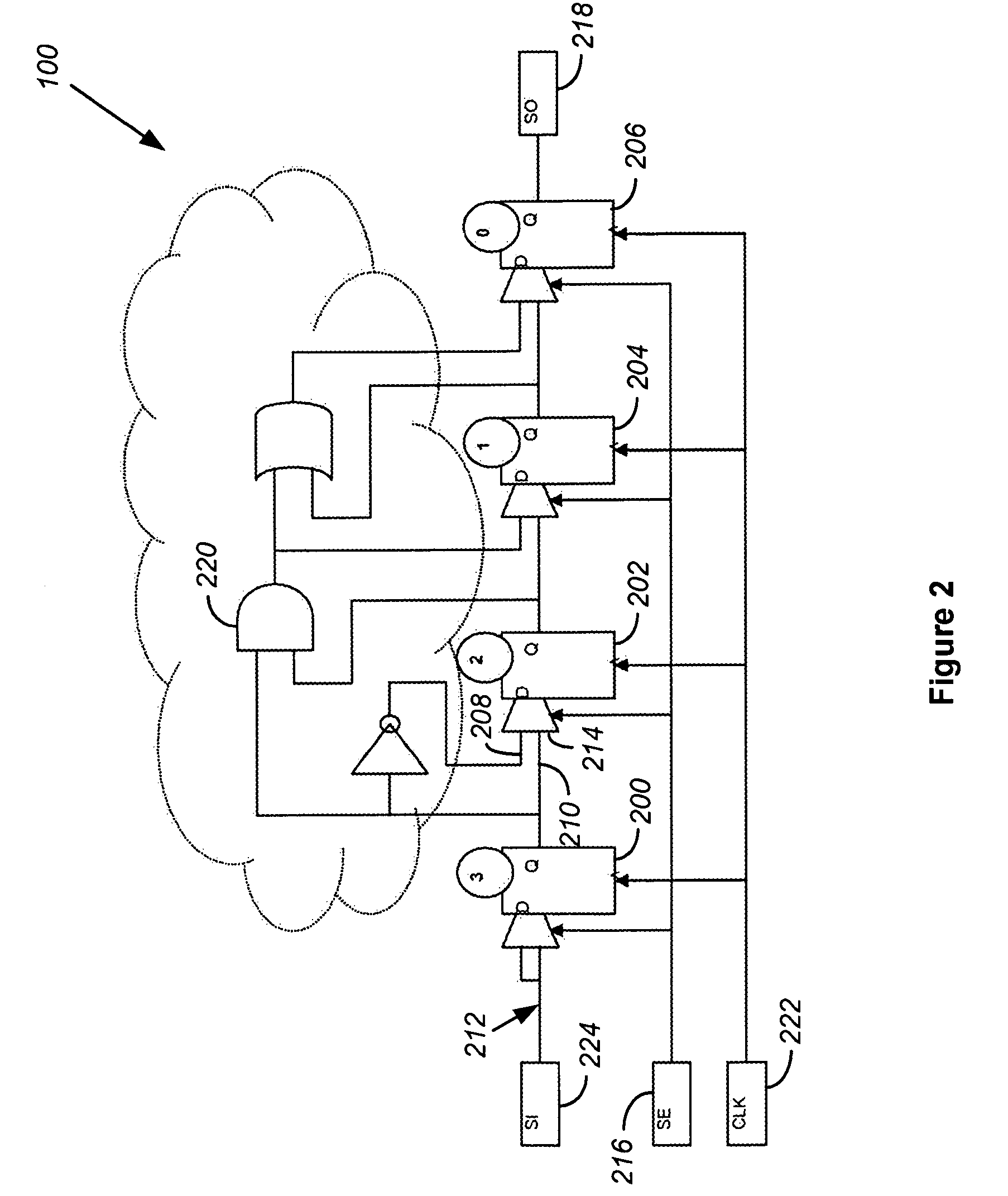
BACKGROUND[0001]To improve the testability of high density semiconductor devices, modern design practice inserts additional circuitry specific to test, such as scan chains. Defects in scan chains are becoming more common as technology nodes decrease in size and the number of flip-flops in a design increase. Problems often surface in scan chains as mission-critical interconnects are routed first, and scan interconnects are routed later to avoid interfering with the mission-critical layout of the device. A scan chain in test mode is configured to be a very long shift register. If a scan chain is blocked, the tester loses observability and controllability within the circuit and records a massive amount of failures.[0002]As technology nodes shrink, more defects are found in the scan chain circuitry added for the purpose of test. This is due to a number of reasons as described in this document. To bring new integrated circuits to market, and ramp yield to acceptable levels, identifying t...

Claims


Application Information

Patent Timeline
Patent Type & Authority Patents(United States)
IPC IPC(8): G01R31/28G06F7/02
CPCG01R31/318569G01R31/318525
Inventor DOKKEN, RICHARD CCHAN, GERALD SISHII, TAKEHIKO
Owner ADVANTEST CORP
Why Eureka
Try Eureka