
Moment-resisting joint and system

a moment-resisting joint and joint technology, applied in the direction of bridges, basic electric elements, constructions, etc., can solve the problems of reducing the ultimate strength and yield strength, and most of the additional features are not always possible in conventional aluminum welded structures, so as to achieve convenient and convenient transportation

Active Publication Date: 2009-08-04
DE LA CHEVROTIERE ALEXANDRE
View PDF37 Cites 9 Cited by
  • Summary
  • Abstract
  • Description
  • Claims
  • Application Information

AI Technical Summary

Benefits of technology

"The invention is a connection system for use in pony-truss bridges that can be quickly assembled from pre-fabricated or off-the-shelf components. The system includes a novel framing element and a method of assembling it. The framing element is designed to resist bending moments and can be attached to the tension chord of the pony-truss bridge using bolts or rods. The connection system can be used in a variety of structures, such as half-through bridges, and can provide better access for pedestrians and bicycles. The invention allows for moment resisting in pony-truss bridges and can be easily assembled and carried by relatively few people."

Problems solved by technology

However, it is well known in literature that aluminum fusion welding partially anneals the weld zone by creating a heat-affected-zone on the base metal which decreases its ultimate and yield strengths (example can be read in Dispersoid-Free Zones in the Heat-Affected Zone of Aluminum Alloy Welds—B. C. MEYER, H. DOYEN, D. EMANOWSKI, G. TEMPUS, T. HIRSCH, and P. MAYR).
Most of these additional features are not always possible for conventional aluminum welded structures since large structures request special transportation or would not fit into anodizing baths or on automated bake paint lines.

Method used


Image

  • Moment-resisting joint and system
  • Moment-resisting joint and system
  • Moment-resisting joint and system

Examples


Embodiment Construction

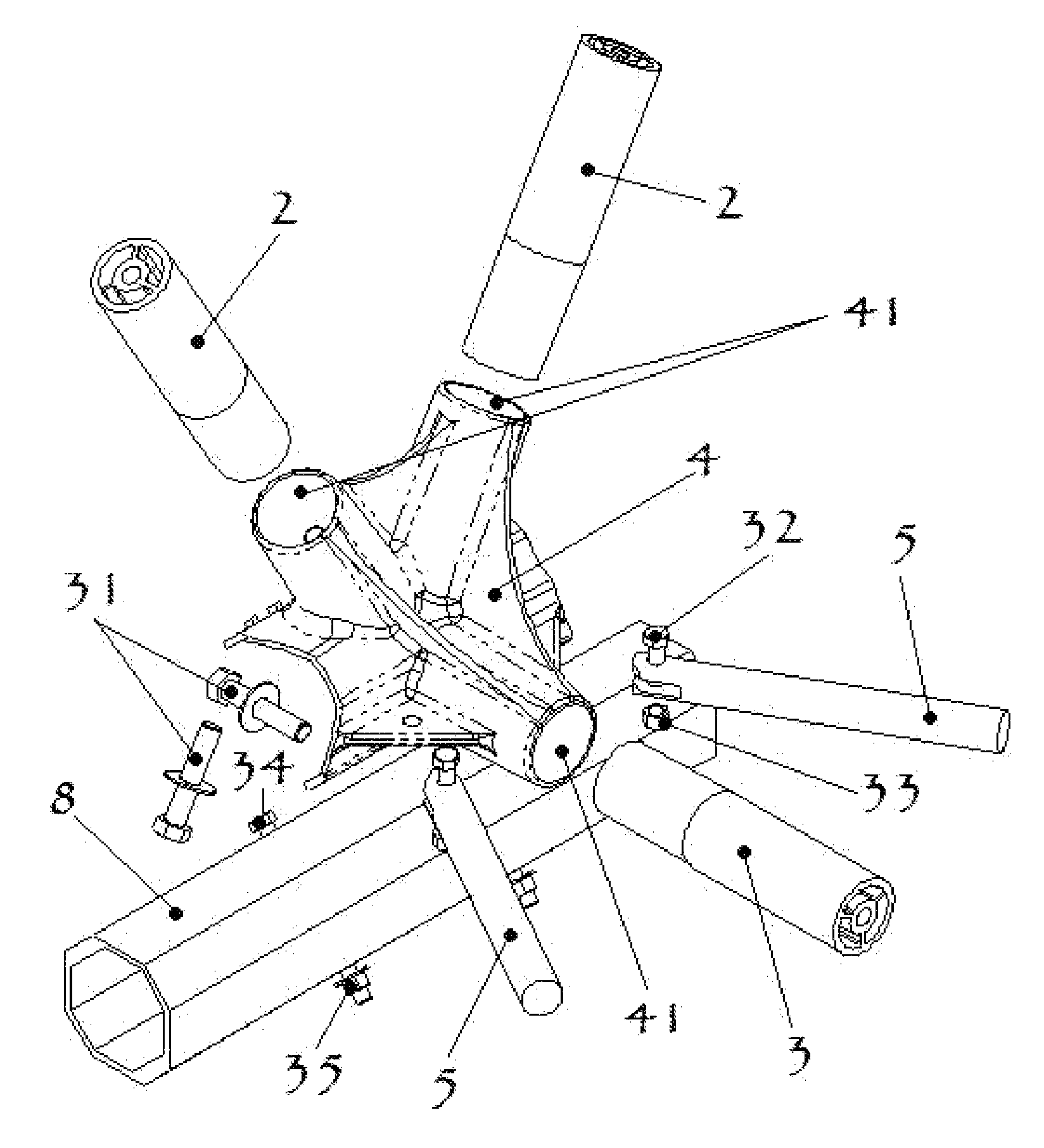
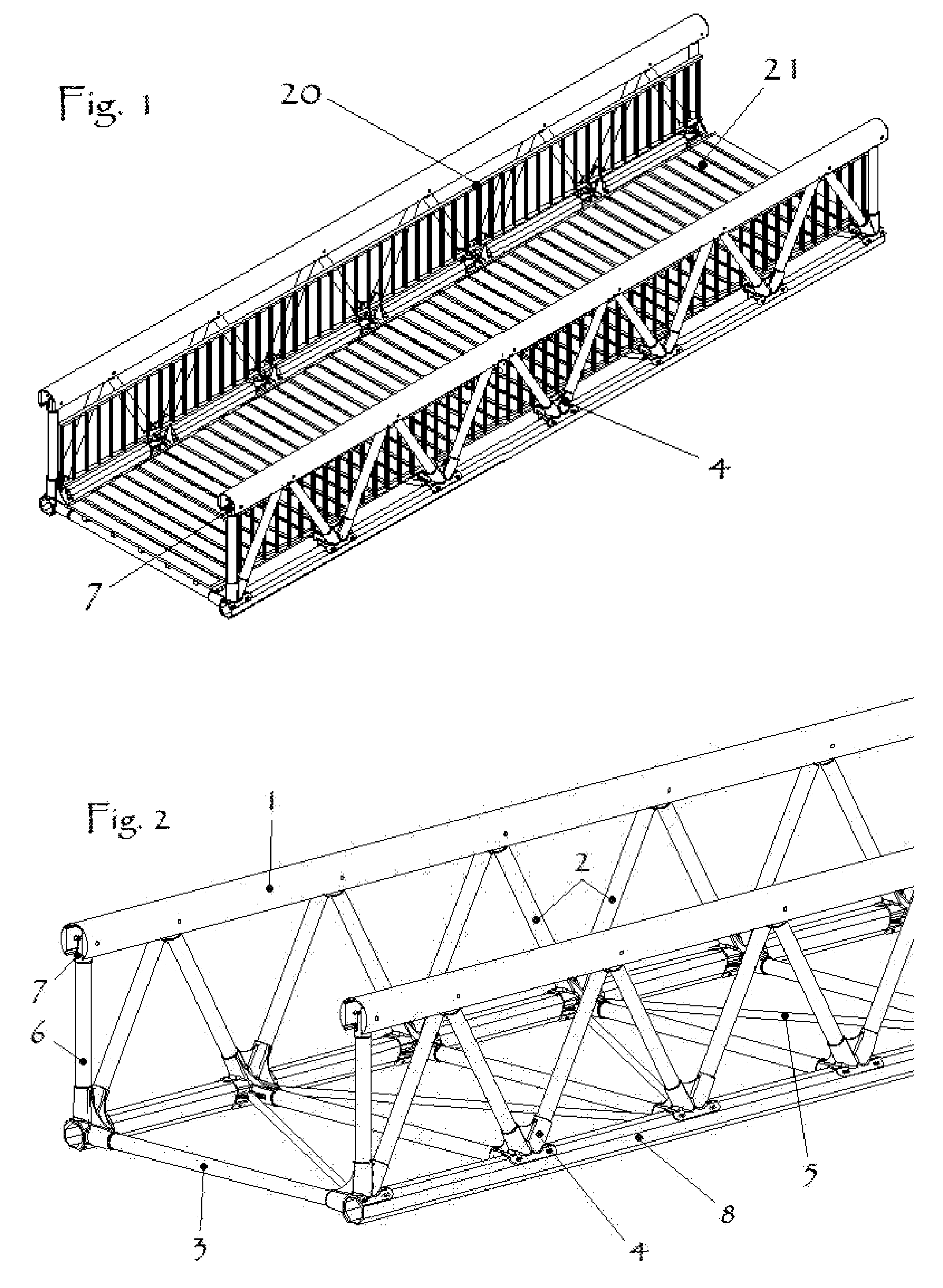
[0058]Turning to FIG. 1, a modular pedestrian bridge 1 is shown comprising a plurality of individual elements connected to each other by the mean of node connectors 4 and 7. Fencing 20 connect to the vertical trusses on the inside as shown or eventually on the outside. A decking 21, or eventually floor boards, is placed on top of the stringers (not shown) and acts as a floor to be walked on. Ends of the bridge, when installed, are connected to respective end footings (not shown) via respective anchors (not shown).

[0059]The modular sections of fencing 20 may be fabricated to any suitable length. Typical sections contemplated are 5 feet, 10 feet, 15 or 20 feet in length.

[0060]FIG. 2 shows the bridge in FIG. 1 prior to installation of the decking and stringers. As can be seen from FIG. 2, both vertical trusses are linked to each other via a plurality of transversals 3 and diagonals 5 extending there between.

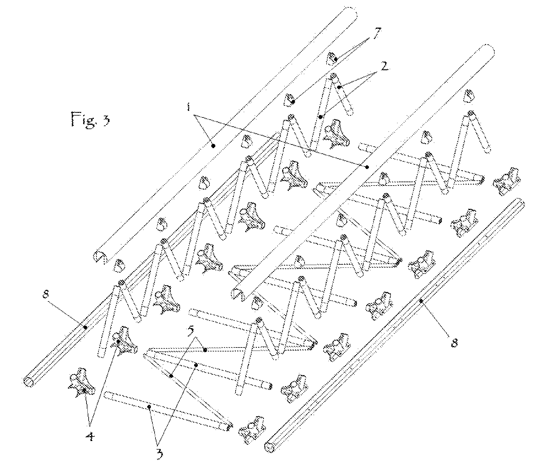
[0061]FIG. 3 illustrates an exploded view of the main bearing structure compris...


PUM


Abstract

The present invention is directed toward a novel moment resisting connection system, for use, but not limited to, with a pony-truss bridge system. The connection system comprises multi-hollow sections that can be, but are not limited to, extruded aluminum and a joint or node connector that can be casted, milled, forged or made by any other means.

Description

CROSS-REFERENCE TO RELATED APPLICATIONS[0001]The present application claims the right of foreign priority with respect to application Ser. No. U.S. 60 / 679,884, filed May. 12, 2005, in United States of America, the disclosure of which is incorporated herein by reference.FIELD OF THE INVENTION[0002]The present invention relates to a non-welded, structural connection system with moment resisting capability that can be used in a pony-truss bridge system or in diverse areas of architectural design, engineering, fabrication, and field erection structures using tubular members.BACKGROUND OF THE INVENTION[0003]Transportable and assemblable bridges are known which can provide a path for pedestrian, bicycles, light or heavy vehicles, across and over obstacles such as rivers and ravines. Some example of previous invention of prefabricated unit construction modular bridging systems may be found in U.S. Pat. Nos. 4,912,795 / 5,414,885 / 6,009,586 / 4,965,903 / 6,308,357 / 6,631,530 and 5,924,152.[0004]Mo...

Claims


Application Information

Patent Timeline
Patent Type & Authority Patents(United States)
IPC IPC(8): E01D19/00
CPCE01D6/00E01D15/133E01D2101/30Y10T403/44E04B2001/2406E04B2001/2451E04B1/585
Inventor DE LA CHEVROTIERE, ALEXANDRE
Owner DE LA CHEVROTIERE ALEXANDRE
Learn More