Hydraulic rescue tool

a technology of hydraulic rescue and tool, applied in the direction of forging presses, forging/pressing/hammering apparatuses, drawing dies, etc., can solve the problems of insufficient power to achieve, excessive weight of emergency personnel to efficiently handle tools, leakage or even catastrophic failure, etc., to prevent overpressurization and storage. easy

Inactive Publication Date: 2009-08-04
FIVE STAR IP HLDG
View PDF15 Cites 56 Cited by
  • Summary
  • Abstract
  • Description
  • Claims
  • Application Information

AI Technical Summary

Benefits of technology

[0023]Of less importance but potentially injurious is a pinch point located between the ears or pivot points and the links, which has been eliminated by encapsulating the joint with an integral barrier at the point of movement. Another possible concern is the pinching of the rear handle against a solid object since prior art handles are usually rigid. The rear handle of the instant invention is spring-loaded to yield, within limitations, thereby reducing, if not completely eliminating the pinching effect. The front handle has likewise been improved by using a bracket that is collapsible, which moves out of the way when engaging a solid structure and yet is positioned with a detent when used in an upright position.
[0024]Additionally, pressure relief valves are provided to limit the hydraulic pressure on either side of the piston rod for pushing and pulling actions, thereby preventing over pressurization.
[0025]Still another object of the invention is also related to the collapsible handle advantage as the handle may pivot down on an enlarged portion of the cylinder body when working in tight areas. The size of the thrust apparatus limits the ability to reach damaged areas in the vehicle structure.
[0026]Another advantage of the tool is the ability to fold down the front handle so that storage is easier, as storage areas in emergency vehicles are usually limited.

Problems solved by technology

The problem with hydraulic rescue tools in the past has been insufficient power to accomplish the task at hand and excessive weight for emergency personnel to handle the tool efficiently.
Further, mechanical structures of the tools now employed for this purpose are being flexed each time the tool is required to be fully loaded, thereby causing the cylinder to be oblonged at the front in time, which creates leaks or even catastrophic failures with continued use when the higher force loads are required.
The most serious problem is that many of the rescue tools in production today simply do not have the mechanical advantage and power required to handle the rescue tasks.

Method used


Image

  • Hydraulic rescue tool
  • Hydraulic rescue tool
  • Hydraulic rescue tool

Examples


embodiment 94

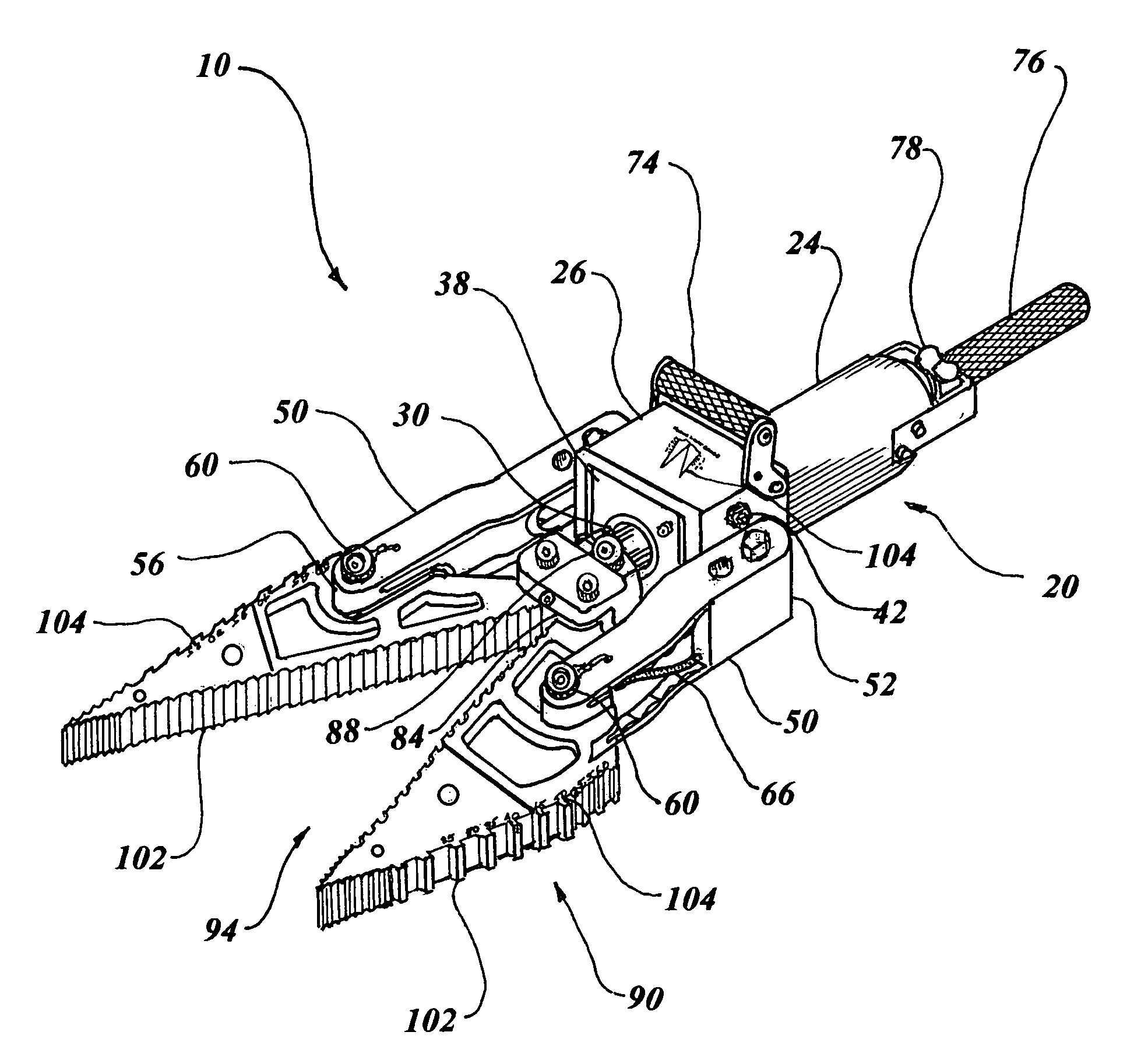
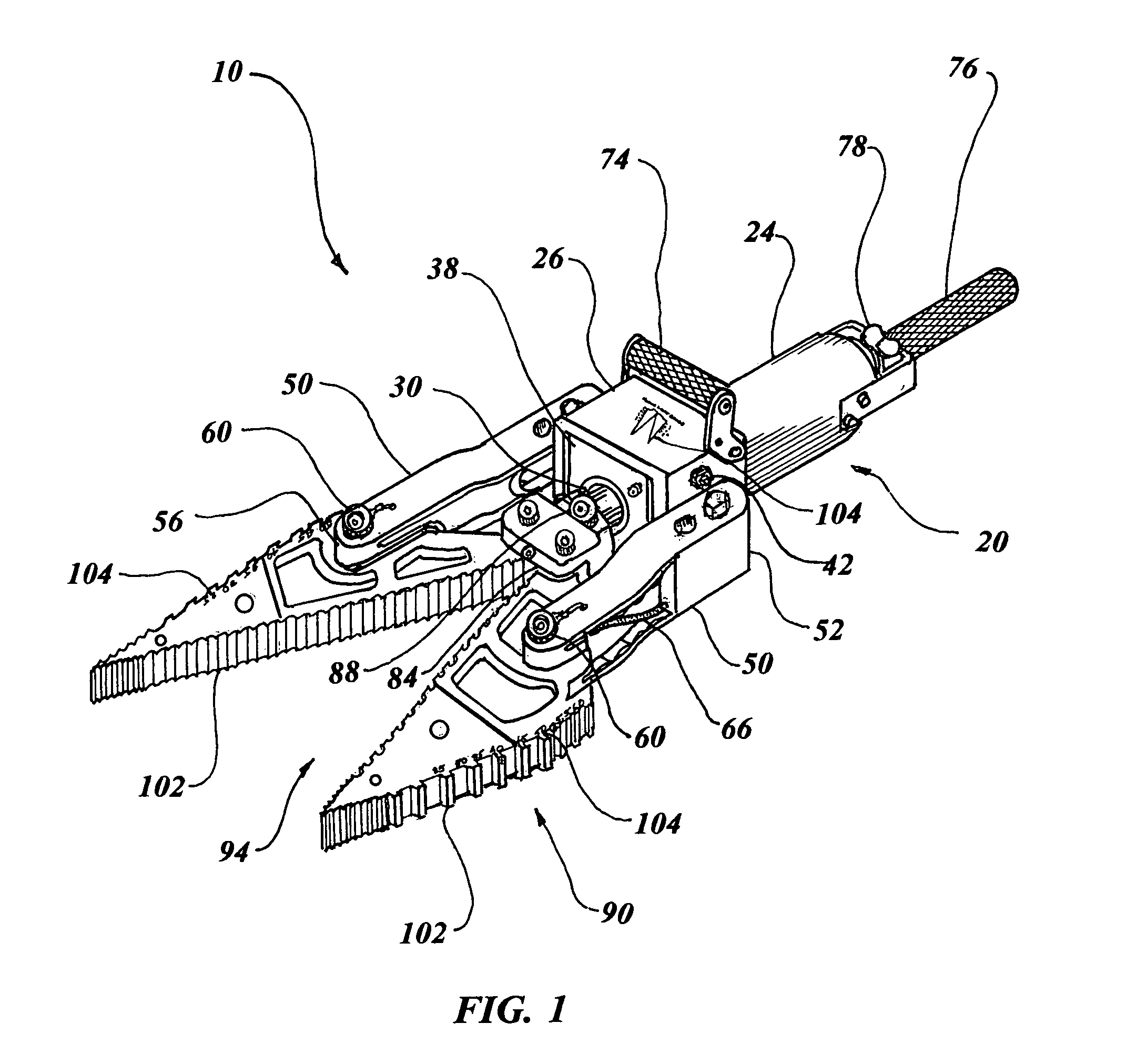
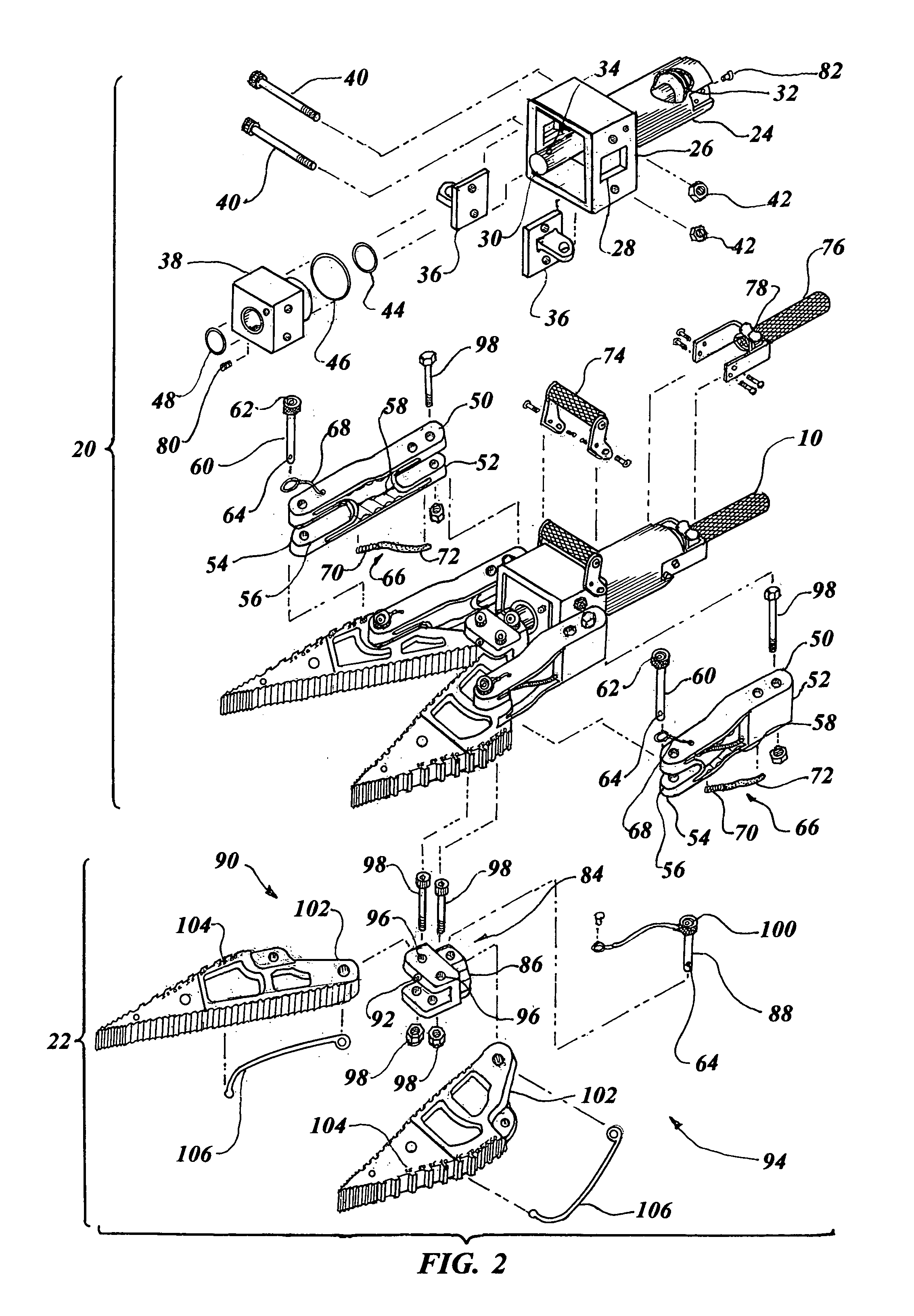
[0062]The vehicle structure separating apparatus 90 in the spreader arm embodiment 94 consists of a pair of opposed spreader arms 102 attached to the yoke 84 and also each connecting link 50. Each spreader arm 102 consists of a steel spreader member having full length teeth and annealed tips that are pinned and bonded to a spreader arm aluminum body.

[0063]The spreader arms 102 contain force load gauge indicia 104 on an exposed surface to indicate the amount of force available at a given point relative to a pivot point distance. Each arm 102 incorporates an internal energy absorbing member 106 disposed in a groove flush with an underside external surface. Alternately, the force load gauge indicia 104 may be etched, silk screened, stenciled or attached with a decal, name plate, or the like, to any part of the hydraulic rescue tool 10 displaying the same information, as illustrated in FIG. 1. The energy absorbing member 106 is preferably constructed of flat malleable mild steel welded ...

embodiment 108

[0065]The tethered yoke pin 88 in this cutter jaws embodiment 108 includes a self-contained third LED 100 within a head portion of the pin 88 and an adjustable ball lock detent 64 on the opposite end.

[0066]The vehicle structure separating apparatus 90 specifically consists of a pair of cutting blades 126 with each cutting blade 126 having a top member 128 and a bottom member 130. The two members 128, 130 are attached together to form a double thick blade with the top member 128 smaller than the bottom member 130 and the bottom member 130 having an annealed tip. Each member incorporates an internal energy absorbing member 106 disposed flush on an underside surface. The internal energy absorbing member 106 is constructed of flat malleable mild steel, welded in place on an interface surface to the one of the members 128 and 130. The double thick cutting blades 126 engage together in mirror image sets such that the bottom members 130 engage contiguously.

[0067]Force load gauge indicia 10...

sixth embodiment

[0082]The quick disconnect implement unit 22 in the sixth embodiment, as illustrated in FIGS. 11 and 12, is designated as the reverse cutting guillotine head 186. In this embodiment the yoke 84 is connected to the piston rod 30 and a hooked blade 188 is attached to the yoke 84. A slotted barrier block 190 is configured to permit the hooked blade 188 to pass through when the hook end of the blade 188 surrounds a workpiece and is pulled into the slotted barrier block 190, a severing action occurs such as that created by a guillotine.

[0083]The yoke 84 is configured with unitary steel construction with a flattened hub attached to the piston rod 30. The tethered yoke pin 88 has a self-contained third LED light 100 within a head portion of the pin 88 and an adjustable ball lock detent 64 on the distal end.

[0084]The yoke 84 in this embodiment is different than the previous embodiments in that it is specifically designated as a blade containing yoke 192 configured with an integral elongated...


PUM

PropertyMeasurementUnit
thickaaaaaaaaaa
Rockwell hardnessaaaaaaaaaa
hydraulic pressureaaaaaaaaaa

Abstract

A hydraulic rescue tool (10) is comprised of a hydraulic thrust apparatus (20) consisting of a hydraulic cylinder body (24) having slots (28) within a hollow end and interlocking ears (36) protruding from the slots. A gland (38) is interfaced between the ears, with the gland and ears connected to the cylinder hollow end with threaded fasteners (98). A connecting link (50) is attached to each interlocking ear and a quick disconnect implement unit (22) is attached to each link and to a piston rod (30) within the cylinder body (24). Six dissimilar embodiments of implement units, each having quick disconnect capabilities and different vehicle structure separating utility are attached to the hydraulic thrust apparatus (20).

Description

TECHNICAL FIELD[0001]The invention generally pertains to rescue tools for emergency operations, and more specifically to a hydraulic tool that is designed to sever material, pry apart structural elements and crush material to rescue a person that is trapped in a damaged vehicle.BACKGROUND ART[0002]Previously, many types of rescue tools have been used to provide an effective means to pry or cut open damaged vehicles at the scene of an accident. Further, other machine tools have been developed with similar operational characteristics.[0003]A search of the prior art did not disclose any patents or industry literature that read directly on the claims of the instant invention. However, the following U.S. patents are considered related:[0004]U.S. Pat. No.InventorIssue Date3,819,153Hurst et al.Jun. 25, 19744,333,330PorterJun. 8, 19824,392,263AmorosoJul. 12, 19834,734,983BrickApr. 5, 19885,301,533JacksonApr. 12, 19945,544,862HickersonAug. 13, 19965,622,353Painter et al.Apr. 22, 19975,956,99...

Claims


Application Information

Patent Timeline
Patent Type & Authority Patents(United States)
IPC IPC(8): B21C3/02B21C3/06B21J9/18
CPCA62B3/005Y10S72/705
Inventor PATTON, TOMMY L.HAGBLOOM, EDWARD H.
Owner FIVE STAR IP HLDG
Why Eureka
Try Eureka