Fluid dynamic pressure bearing, motor, and recording medium driving device

a technology of dynamic pressure bearing and driving device, which is applied in the direction of sliding contact bearing, record information storage, instruments, etc., can solve the problems of too shallow dynamic pressure generating groove formation, failure to provide a radial direction escape place for the part positioned inside, and failure to prevent bubble generation and oscillation. , the effect of preventing errors

Inactive Publication Date: 2009-08-04
SAMSUNG ELECTRO MECHANICS CO LTD
View PDF23 Cites 11 Cited by
  • Summary
  • Abstract
  • Description
  • Claims
  • Application Information

AI Technical Summary

Benefits of technology

[0013]The present invention has been made in view of the above circumstances, and therefore has an object to provide a fluid dynamic pressure bearing whereby the generation of bubbles can be suppressed by enabling the dynamic pressure generating grooves in the end face of the thrust bearing plate to be formed to a uniform depth by a press operation, and enabling a stable supply of working fluid to the dynamic pressure generating grooves, and oscillation at the time of rotation and leakage of working fluid can be prevented effectively by efficiently releasing any bubbles generated, and to provide a motor, and a recording medium driving device.

Problems solved by technology

In the case where the dynamic pressure generating grooves are formed on the end faces of the thrust bearing plate by a press operation, if there is no place for the material forming the thrust bearing plate to escape, there is an inconvenience in that dispersion occurs in the depth of the dynamic pressure generating grooves formed.
However, there is no place for the part positioned inside in the radial direction to escape.
As a result, the dynamic pressure generating grooves are formed too shallow.
Therefore, even if it is possible for working fluid to be supplied from the other end face side of the thrust bearing plate via the through holes provided in the ring grooves, a problem can be envisaged in that the working fluid in the through holes is obstructed by the step difference during start up, making it difficult for it to enter the gap between the shaft and the flange in the ring region.
When bubbles are generated, the lubrication properties of the working fluid diminish, and the rotation becomes unstable.
Therefore there are inconveniences of oscillation occurring and the like.
Moreover, since the liquid surface of the working fluid rises due to the generation of bubbles, an inconvenience of leakage out of the housing can also be envisaged.

Method used


Image

  • Fluid dynamic pressure bearing, motor, and recording medium driving device
  • Fluid dynamic pressure bearing, motor, and recording medium driving device
  • Fluid dynamic pressure bearing, motor, and recording medium driving device

Examples


first embodiment

[0047]Hereunder is a description of a fluid dynamic pressure bearing, a motor, and a recording medium driving device according to the present invention, with reference to FIG. 1 to FIG. 4.

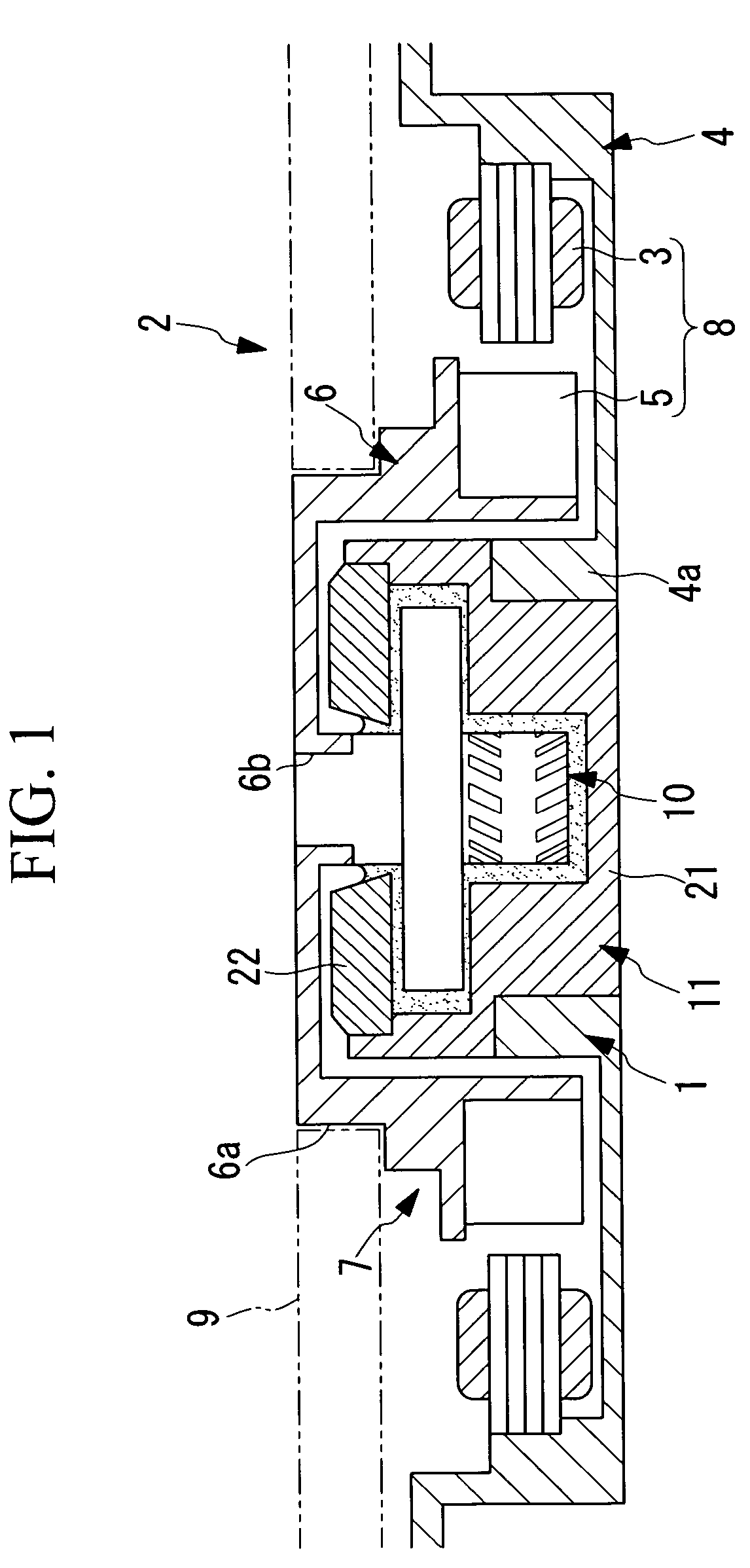
[0048]A fluid dynamic pressure bearing 1 according to the present embodiment is used in a recording medium driving device 2 as shown in FIG. 1. The recording medium driving device 2 is provided with a motor 7 comprising a stator 4 having coils 3 arranged in an annular shape, a rotor 6 that is located inside of the stator 4 and has permanent magnets 5 located opposite the coils 3, and a fluid dynamic pressure bearing 1 that supports the rotor 6 such that it can rotate with respect to the stator 4. A driving device 8 which rotates the rotor 6 with respect to the stator 4, is configured by the coils 3 provided in the stator 4 and the permanent magnets 5 provided in the rotor 6.

[0049]The rotor 6 is provided with a fitting section (fastening section) 6a onto which a ring-shaped recording medium 9 is fit...

embodiment 1

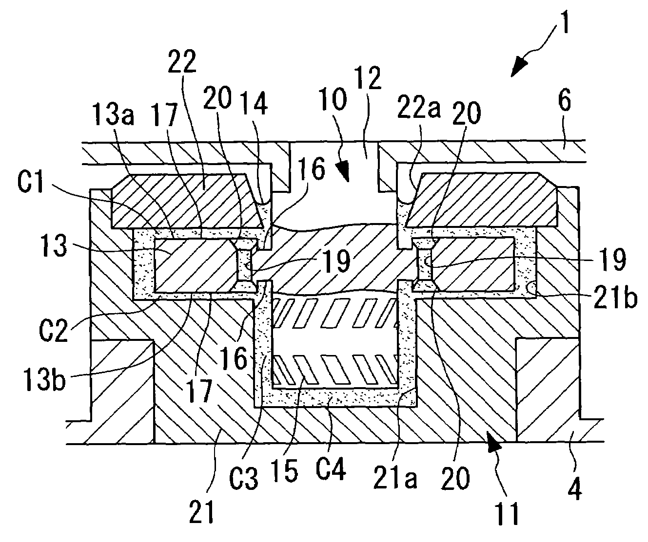
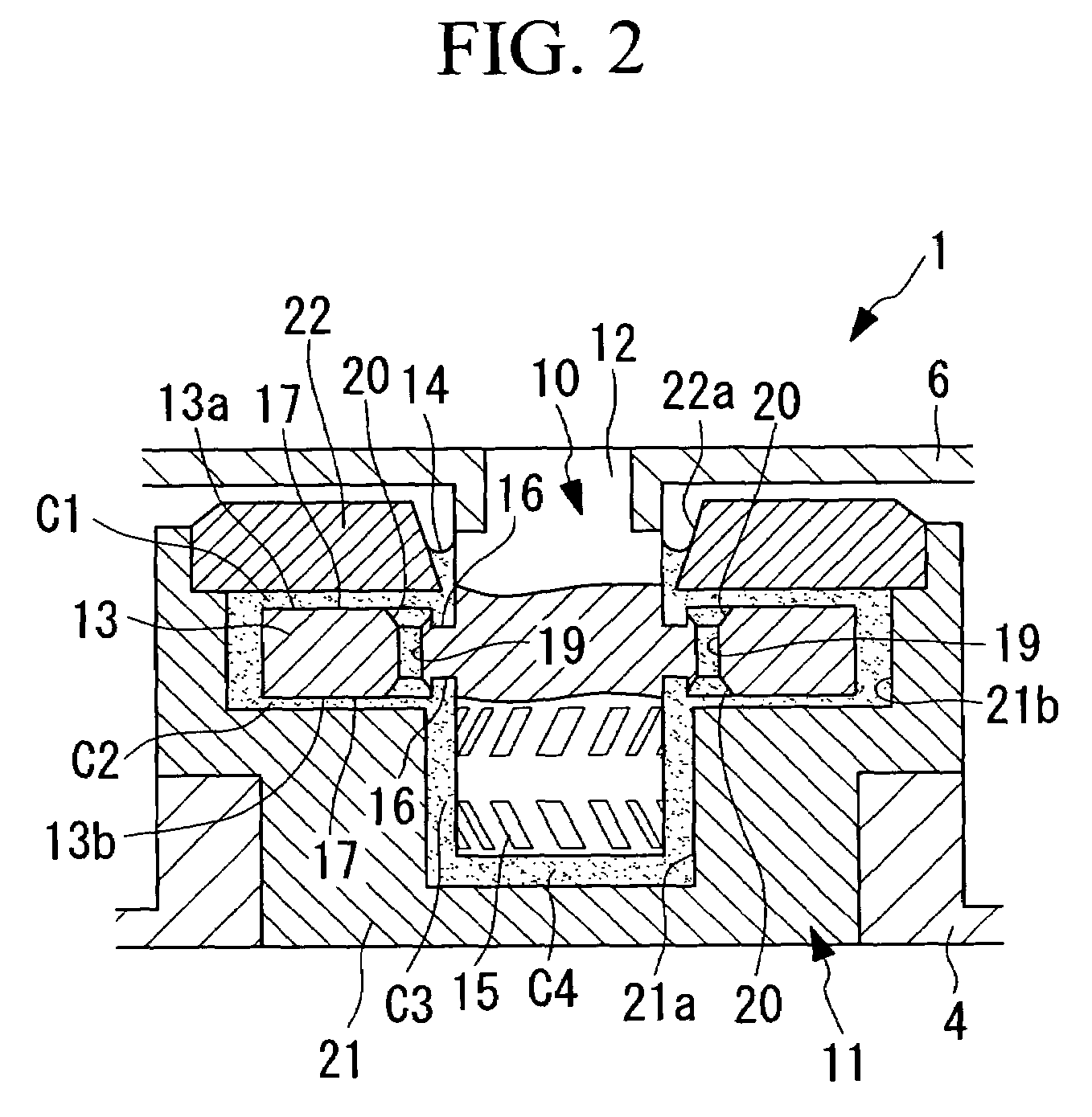
[0051]As shown in FIG. 2, the fluid dynamic pressure bearing 1 according to the present embodiment 1 comprises; a shaft 10 having a substantially cylindrical shaft body 12 and a flange shaped thrust bearing plate 13 that extends all around its peripheral surface in the radial direction located in an axial midway position of the shaft body 12, and a housing 11 for housing the shaft 10. The housing 11 is provided with an inner surface arranged with a minute gap with respect to the outer surfaces of the shaft 10, and the gap between the inner surface and the outer surface of the shaft 10 is filled with oil (working fluid) 14.

[0052]The shaft body 12 and the thrust bearing plate 13 are integrated. A plurality of radial dynamic pressure generating grooves 15, which are called herringbone grooves, is formed on the outer peripheral surface of the shaft body 12, located on one side of the thrust bearing plate 13 in the thickness direction. The radial dynamic pressure generating grooves 15 ar...

second embodiment

[0077]Next is a description of a fluid dynamic pressure bearing, a motor, and a recording medium driving device according to the present invention with reference to FIG. 11 and FIG. 12.

[0078]In the description of the present embodiment, the same symbols are used for those parts whose structures are common to the first embodiment, and the descriptions are omitted.

[0079]A recording medium driving device 101 according to the present embodiment differs from the recording medium driving device 2 according to the first embodiment in the construction of a fluid dynamic pressure bearing 102.

[0080]As shown in FIG. 11, the fluid dynamic pressure bearing 102 according to the present embodiment is provided with a substantially cylindrical shaft body 104 which is formed integral with a rotor (shaft) 103, a housing 106 which has a shaft body insertion hole 105 for accommodating the shaft body 104 rotatably and is fixed in a stator 4, and a detachment prevention member 107 which is fixed to the ro...


PUM

PropertyMeasurementUnit
thicknessaaaaaaaaaa
pressureaaaaaaaaaa
depthaaaaaaaaaa

Abstract

A fluid dynamic pressure bearing has an annular dynamic pressure generating face having a dynamic pressure generating groove, which draws a working fluid toward a midway position in the radial direction from the inside and outside of a thrust bearing plate in the radial direction when a shaft and a housing are rotated relative to each other. The dynamic pressure generating groove is provided on thickness direction end faces of the thrust bearing plate or on an inner surface of the housing, and an inner groove section is located on an inner peripheral side of the dynamic pressure generating face on the end faces and is recessed more than the dynamic pressure generating face in the thickness direction. A through-hole extends through the thrust bearing plate in the thickness direction so as to open to the dynamic pressure generating face, and a communicating cavity connects the opening portion of the through-hole and the inner groove section.

Description

CROSS REFERENCE TO RELATED APPLICATIONS[0001]This application is a U.S. national stage application of International Application No. PCT / JP2005 / 002491, filed Feb. 17, 2005, claiming a priority date of Feb. 18, 2004, and published in a non-English language.BACKGROUND OF THE INVENTION[0002](a) Field of the Invention[0003]The present invention relates to a fluid dynamic pressure bearing, a motor, and a recording medium driving device.[0004](b) Description of Related Art[0005]Up to now, as this type of fluid dynamic pressure bearing, there are ones with the constructions disclosed in, for example, Japanese Unexamined Patent Publication No. 10-196643 (Patent Document 1) and Japanese Unexamined Patent Publication No. 10-213133 (Patent Document 2).[0006]In this type of fluid dynamic pressure bearing, the gaps between the shaft and housing are filled with working fluid, and the shaft is supported rotatably relative to the housing, while maintaining the shaft and the housing such that they do...

Claims


Application Information

Patent Timeline
Patent Type & Authority Patents(United States)
IPC IPC(8): F16C32/06F16C17/04F16C17/10F16C33/10G11B19/20H02K7/08
CPCF16C17/107F16C33/107G11B19/2009F16C33/1085F16C17/045H02K7/085F16C2370/12
Inventor GOTOH, HIROMITSUOGUCHI, KAZUAKIKINOSHITA, SHINJITAZAWA, CHIHIROHAYASHI, TOMOHIKO
Owner SAMSUNG ELECTRO MECHANICS CO LTD
Why Eureka
Try Eureka