Laser drilling system and method

a laser drilling and laser technology, applied in the field of laser drilling system and method, can solve the problems of excess product loss, no sensor, etc., and achieve the effects of improving system performance, reducing the amount of solids lost, and increasing process efficiency

Inactive Publication Date: 2009-08-04
ACELLA HLDG LLC +1
View PDF12 Cites 17 Cited by
  • Summary
  • Abstract
  • Description
  • Claims
  • Application Information

AI Technical Summary

Benefits of technology

[0012]The present laser drilling apparatus overcomes many of the disadvantages inherent in related prior art apparatuses by reducing the amount of solids lost due to malfunction or misfiring of the laser, by increasing process efficiency and improving system performance. Unlike the known systems, the present system also includes an optional process validation system. According to the embodiment of the invention, the laser apparatus is capable of: 1) immediately returning undrilled solids back to the solids reservoir; 2) detecting the presence of a solid in the solids chamber of an indexer by means other than deflection of the laser beam; 3) detecting the color of the surface of the solid prior to and, optionally, after drilling; 4) rejecting and, optionally, repositioning solids in the solids chamber of the indexer prior to drilling; 5) electronically and, optionally visually, inspecting the surface of the solid shortly after drilling to confirm the presence of a hole, the location of the hole, the number of holes and / or the shape of the hole; 6) electronically inspecting the surface of the solid to determine its color; 7) validating process performance by employing redundant but different sensing or detection means; 8) providing a summary of system performance for the laser drilling system; 9) synchronizing operation of multiple components of the laser apparatus; and / or 10) drilling tablets in a continuous, semicontinuous or batchwise operation.

Problems solved by technology

This system does not employ a sensor that actually detects the presence of a tablet in the slot of a conveyor, nor does it permit immediate return of undrilled tablets to the tablet reservoir.
This system results in excess product loss due to the number of tablets that pass through the firing zone without being drilled.

Method used


Image

  • Laser drilling system and method
  • Laser drilling system and method
  • Laser drilling system and method

Examples


example 1

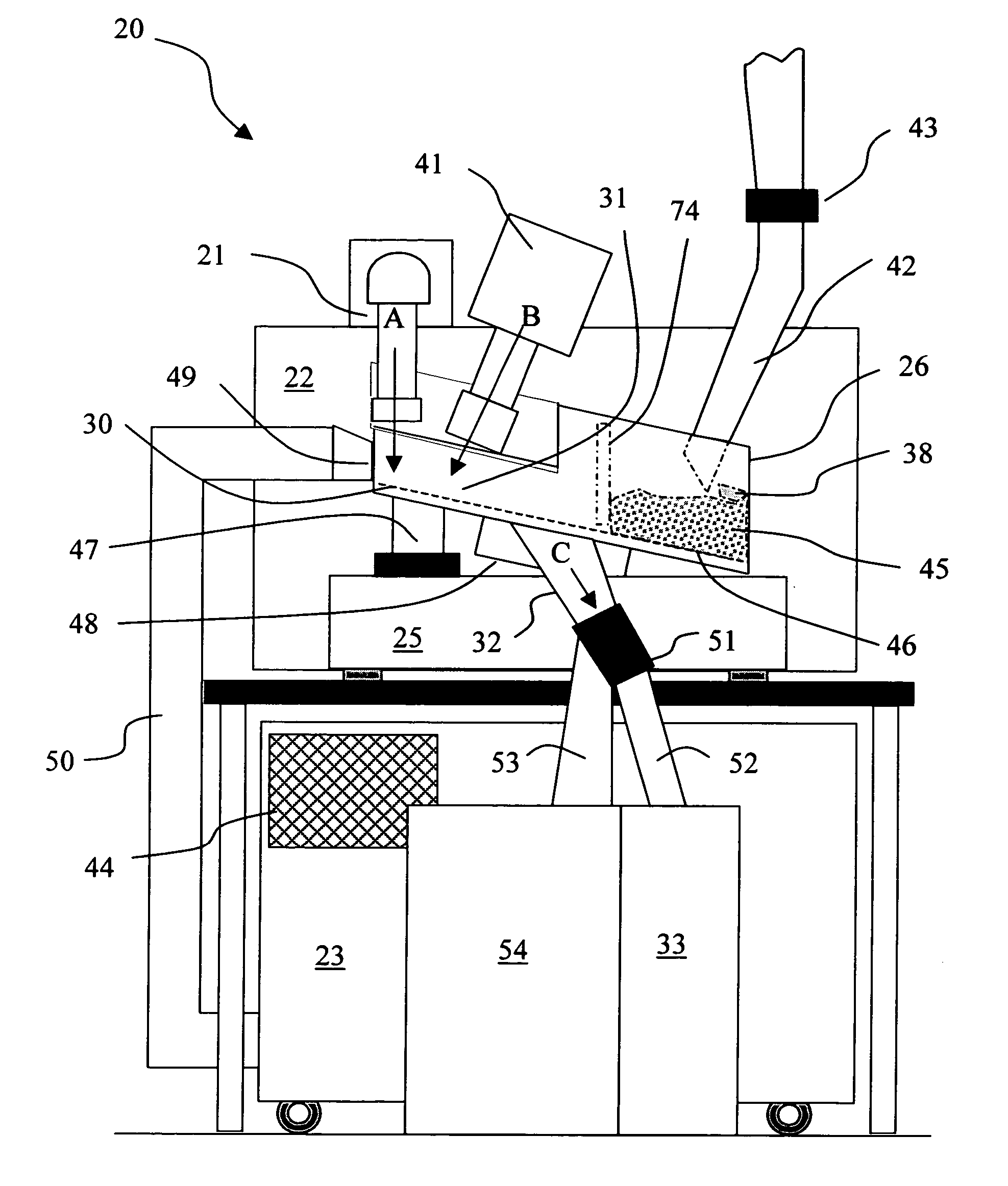
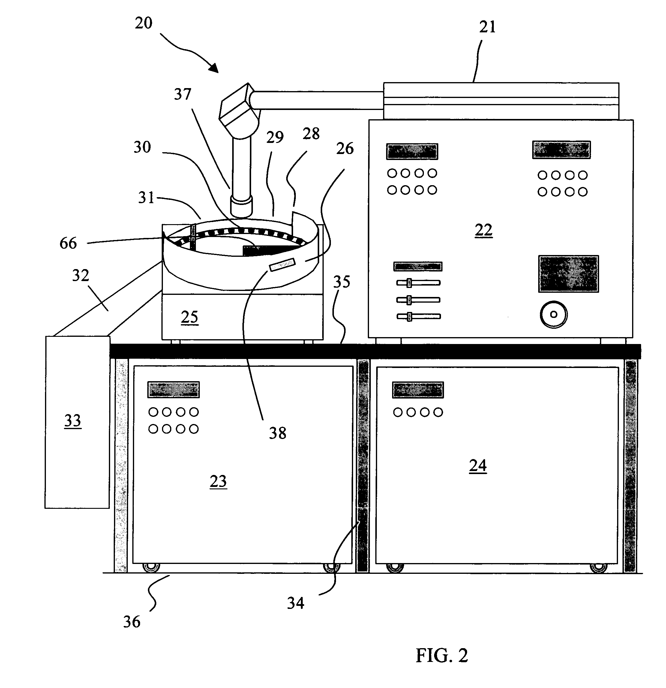
[0165]Osmotic device tablets were drilled with a laser system as follows.

[0166]The indexer having a cradle diameter according to the diameter of the tablet to be drilled, together with the corresponding partitions forming the cradles are set up. The height of the separator is set according to the height of a single tablet being drilled. The corresponding air jets (repositioning means) are assembled. Facility supplies are checked, and then the system is powered up. Air pressure supplied to the air jets is set according to the tablet to be drilled. The rotating disk is set to run, and the synchronism sensor is calibrated by checking the correct position and repositioning it if necessary. Then, the presence sensor position is calibrated by checking the correct position and repositioning it if necessary. Then, the laser device is powered together with the dust cleaner (aspirator). Several tablets are drilled so as to ensure the correct position of the hole on the tablet. If needed, the ...


PUM

PropertyMeasurementUnit
diameteraaaaaaaaaa
time coordinate graphaaaaaaaaaa

Abstract

The present invention provides a laser drilling system for drilling holes or cavities in a solid, in particular a solid dosage form. The system includes a loading zone, firing zone, inspection zone and delivery zone. The system also includes optional components such as a process validation system, solids detector, color detector, solids rejection / repositioning means, accepted products receptacle, rejected products receptacle and / or solids inspection system. Operation of the laser device in the firing zone and of other optional equipment is synchronized with movement of a continuous solids indexer by way of an electronic synchronizer. A solids handling system includes an optional fill level detector that directly or indirectly controls solids loading means that fills a solids reservoir. The system can be run continuously, semicontinuously or batchwise. A solids rejection system in the system provides for reduced solids loss as compared to other laser drilling systems and solids recovery rates of 100% can be achieved.

Description

CROSS-REFERENCE TO EARLIER FILED APPLICATION[0001]The present application is a CONTINUATION-IN-PART of and claims the benefit of earlier filed conventional application Ser. No. 10 / 153,226 filed May 21, 2002 now U.S. Pat. No. 6,809,288, and provisional application for patent Ser. No. 60 / 293,151 filed May 23, 2001.FIELD OF THE INVENTION[0002]This invention pertains to a method of and apparatus for forming cavities on solid formulations. More particularly, it pertains to a method of and apparatus for forming one or more cavities or holes on the surface of a solid formulation, such as a solid pharmaceutical dosage form, by employing a laser device.BACKGROUND OF THE INVENTION[0003]Solid formulations are used for the delivery of active agents to an environment of use. Active agents generally include medicines, nutrients, food products, pesticides, herbicides, germicides, algaecides, chemical reagents, and others known to those of ordinary skill. When a solid formulation includes a core co...

Claims


Application Information

Patent Timeline
Patent Type & Authority Patents(United States)
IPC IPC(8): B41F17/36B23K26/36B65G47/22A61J3/10B23K26/08B23K26/38
CPCA61J3/10B23K26/0853B23K26/381B23K26/4095B23K26/402B23K26/385B23K2203/10B23K26/40B23K26/382B23K26/389B23K2101/35B23K2103/50
Inventor FAOUR, JOAQUINAISERUK, ALEJANDRO
Owner ACELLA HLDG LLC
Why Eureka
Try Eureka