Delay-locked loop and a delay-locked loop detector

Active Publication Date: 2009-08-04
HIMAX TECH LTD
View PDF9 Cites 6 Cited by
  • Summary
  • Abstract
  • Description
  • Claims
  • Application Information

AI Technical Summary

Benefits of technology

[0002]The present invention relates to a delay-locked loop. More particularly, the present invention relates to a delay locked loop detector.
[0013]According to another embodiment of the present invention, the delay-locked loop includes a delay circuit, a voltage detector, a switch, and a counter. The delay circuit generates an output clock signal according to a delay time which is controlled by a control voltage. The switch passes the control voltage to the voltage detector, and the voltage detector detects the control voltage. The counter counts a constant period of time, in which the counter enables the switch to pass the control voltage to the voltage detector after the constant period of time.
[0009]Therefore, there is a need for a new delay-locked loop and a detection circuit thereof which can tell if the DLL is deadlock at wrong frequency and rectify the situation accordingly.

Problems solved by technology

Furthermore, since a lot of circuits are integrated on a chip, the clock signal is entirely distributed on the chip, and clock skew problems arise as a result.
For example, when an input clock drives a chip, an uncertain delay appears between the input clock and the internal clock, which makes the chip work incorrectly.
However, in this conventional DLL, the irregular high supply voltage or a clock signal with many jitters might cause the VCTL to exceed the proper voltage range, and the VCTL is unable to return back to the normal voltage range, which makes the DLL deadlock at the wrong frequency, that is, the DLL cannot generate a clock signal with an expected frequency, and the whole circuit on the chip might operate at the wrong frequency as a result.

Method used


Image

  • Delay-locked loop and a delay-locked loop detector
  • Delay-locked loop and a delay-locked loop detector
  • Delay-locked loop and a delay-locked loop detector

Examples


Embodiment Construction

[0022]Reference will now be made in detail to the present preferred embodiments of the invention, examples of which are illustrated in the accompanying drawings. Wherever possible, the same reference numbers are used in the drawings and the description to refer to the same or like parts.

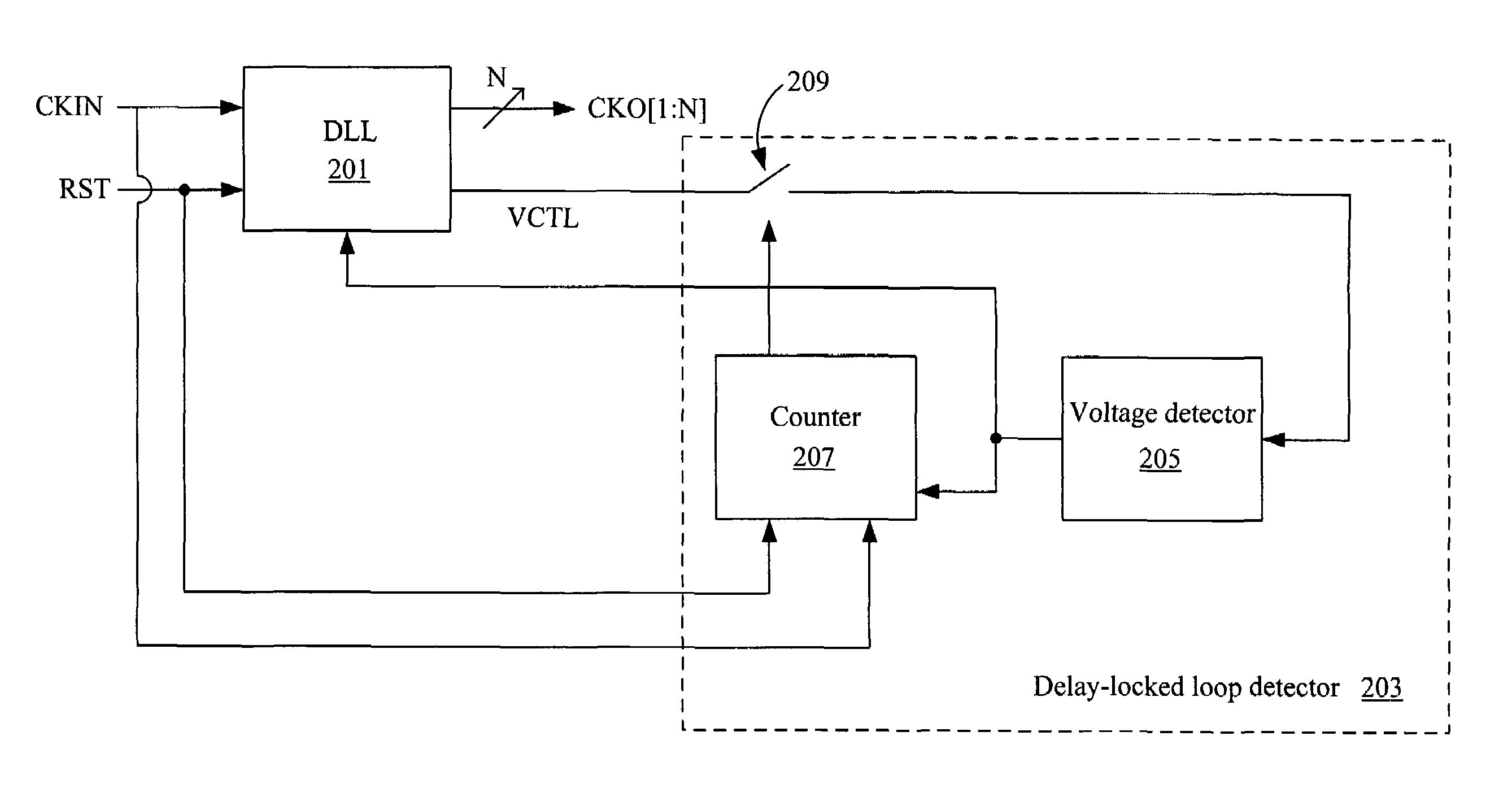
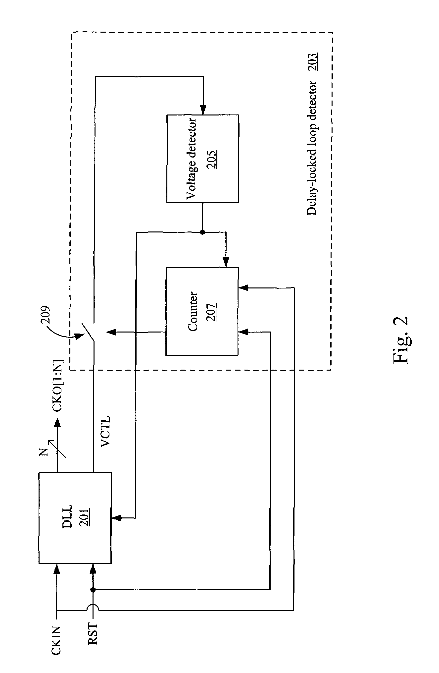
[0023]FIG. 2 shows the block diagram of the delay-locked loop detector and the DLL thereof according to one embodiment of the present invention. The delay-locked loop detector 203 detects the control voltage VCTL used to tune a delay time of a delay-locked loop (DLL) 201, and the output clock signal is controlled according to the delay time. The delay-locked loop detector 203 includes a voltage detector 205, a counter 207, and a switch 209. The switch 209 passes the control voltage VCTL to the voltage detector 205, and the voltage detector 205 detects the control voltage VCTL of the DLL 201 to identify if the voltage level of the control voltage VCTL is out of range. If the control voltage VCTL is ou...


PUM


Abstract

A delay-locked loop detector detects a control voltage of a delay-locked loop, in which the delay-locked loop generates an output clock signal according to a delay time that is controlled by the control voltage. The delay-locked loop detector includes a voltage detector, a switch, and a counter. The voltage detector detects the control voltage. The switch passes the control voltage to the voltage detector. The counter counts a constant period of time, in which the counter enables the switch to pass the control voltage to the voltage detector after the constant period of time.

Description

BACKGROUND[0001]1. Field of Invention[0002]The present invention relates to a delay-locked loop. More particularly, the present invention relates to a delay locked loop detector.[0003]2. Description of Related Art[0004]Recently, with the outstanding improvement of the semiconductor process, the operating frequency of VLSI circuits has increased significantly. High-speed systems such as wireless phones, optical fiber links, microcomputers, and high-end system-on-a-chip (SOCs) have transmission rates at the Giga-Hertz level. Therefore, electronic devices need to upgrade their operating frequency in order to keep up with the improved semiconductor process. Furthermore, since a lot of circuits are integrated on a chip, the clock signal is entirely distributed on the chip, and clock skew problems arise as a result.[0005]For example, when an input clock drives a chip, an uncertain delay appears between the input clock and the internal clock, which makes the chip work incorrectly. In order...

Claims


Application Information

Patent Timeline
IPC IPC(8): H03L7/06
CPCH03L7/0812H03L7/10H03L7/089H03L7/0816
Inventor HUANG, CHIH-HAUR
Owner HIMAX TECH LTD
Why Eureka
Try Eureka