
Arrangement for the wireless connection of terminals to a communication system

a technology for communication systems and terminals, applied in the field of arrangement for the wireless connection of terminals to a communication system, can solve the problems that the use of such a variety of communication and data services using a corresponding variety of wirelessly coupled terminals is only limited, and achieves the effects of small installation size, good cryptographic properties, and high data transmission rates

Inactive Publication Date: 2009-08-04
UNIFY GMBH & CO KG
View PDF33 Cites 2 Cited by
  • Summary
  • Abstract
  • Description
  • Claims
  • Application Information

AI Technical Summary

Benefits of technology

[0010]The coupling of the server and at least one transition device to the data packet network enables the flexibility and large application spectrum of packet-oriented communication networks to be advantageously utilized directly and generically for wireless applications. Because a corresponding packet-oriented communication infrastructure, e.g. in the form of local area networks (LAN) or wide area networks (WAN) is already present in, or being provided in, many places, the invention can generally be implemented at little cost. In particular, a number of the performance features, services and / or applications available in data packet networks of this kind can be used in a relatively simple manner. The arrangement in accordance with the invention thus provides a flexible, expandable, very scaleable, generic platform for using different communication and / or data services by means of wirelessly coupled terminal devices.
[0017]Advantageously, a Bluetooth module can be used as the short-range radio module. Bluetooth modules of this kind have a small installation size, high data transmission rates, good cryptographic properties and high flexibility.

Problems solved by technology

Up until now, however, the utilization of such a variety of communication and data services using a corresponding variety of wirelessly coupled terminals is possible to only a limited extent.

Method used


Image

  • Arrangement for the wireless connection of terminals to a communication system
  • Arrangement for the wireless connection of terminals to a communication system

Examples


Embodiment Construction

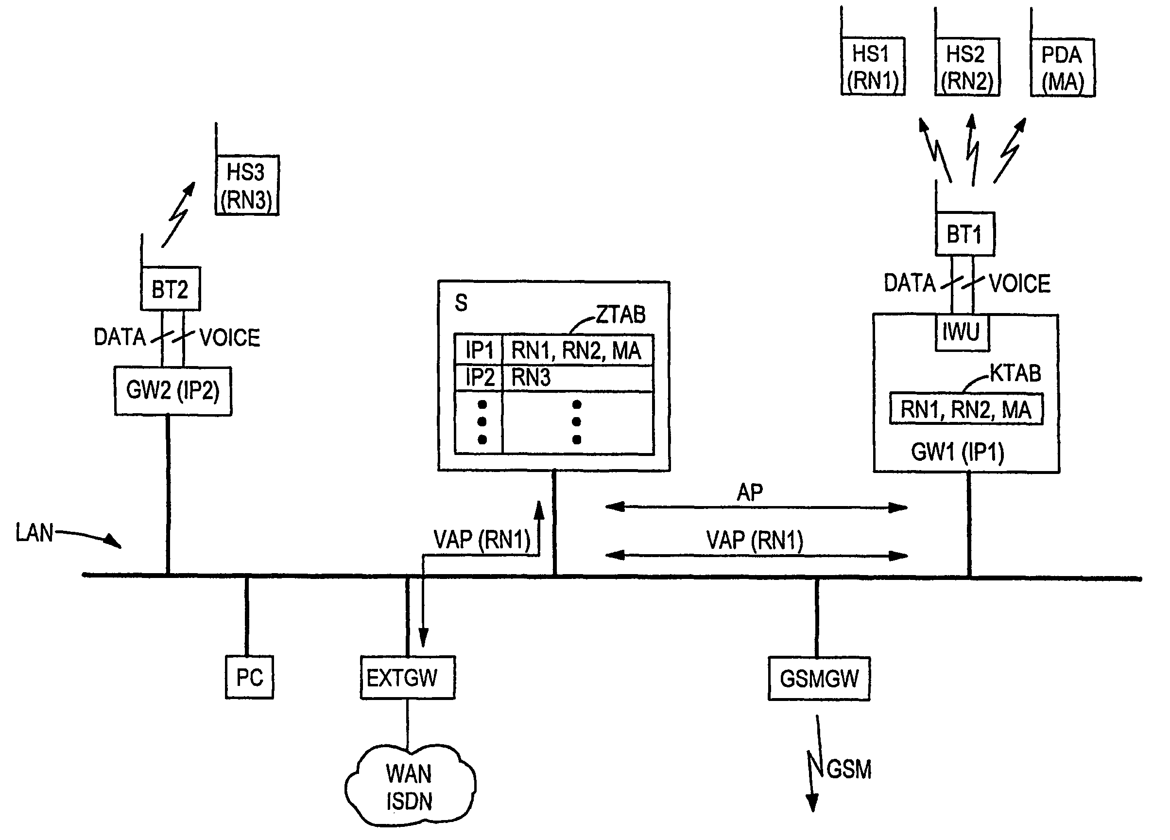
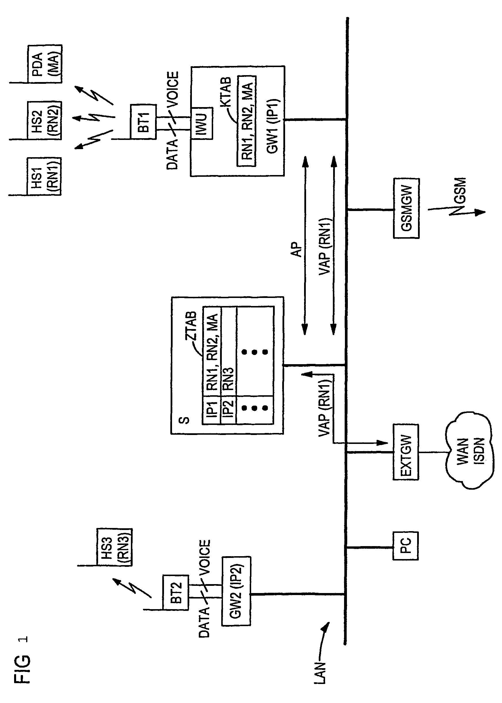
[0023]The drawing is a schematic illustration of a communication system with wirelessly coupled terminal devices that, in the exemplary embodiment shown, are arranged as headsets HS1, HS2, HS3 and PDA. The PDA in the illustration is given the same reference designation. The communication system includes a data packet network LAN, e.g. an Ethernet designed as a local network, the data transmission of which is preferably based on protocols of the TCP / IP family of protocols. Connected to the data packet network LAN is a server S, e.g. a gatekeeper in accordance with ITU-T recommendation H.323, that controls the connections carried in the data packet network LAN, e.g. for voice, video, multimedia and / or data communication and in particular a setup of such connections. This control preferably takes place by means of client-server structures based on Internet protocols. Connections to voice, video and / or multimedia communication via local networks based on Internet protocols are frequentl...


PUM


Abstract

The aim of the invention is to connect terminals to a communication system in a wireless manner by means of a data packet network. At least one transition device to which a short-range radio module is coupled, and a server for controlling connections to the terminals, are coupled to said data packet network. The transition device is provided with a coupling table comprising addresses of terminals which are situated within the radio coverage of the short-range radio module. The server comprises an allocation table in which a network address of the transition device which enables the terminal to be wirelessly reached is respectively allocated to an address of a terminal. According to the invention, a packet-based alignment protocol is provided in order to dynamically align the allocation table with the coupling table.

Description

CROSS REFERENCE TO RELATED APPLICATIONS[0001]This application is a continuation of International Application No. PCT / DE02 / 02836, filed Aug. 1, 2002 and claims the benefit thereof. The International Application claims the benefits of German application No. 10142007.2 filed Aug. 28, 2001, both of the applications are incorporated by reference herein in their entirety.FIELD OF INVENTION[0002]The invention relates to an arrangement for the wireless connection of terminals to a communication system.BACKGROUND OF THE INVENTION[0003]With present communication systems, terminals that can serve a variety of purposes, such as the transmission of a voice, video, multimedia, fax, file, program and / or measuring data are increasingly coupled wirelessly. In the meanwhile, a variety of different radio network technologies such as GSM (Global System for Mobile Communication), DECT (Digital Enhanced Cordless Telephony), and particularly Bluetooth, have been developed from this for different fields of...

Claims


Application Information

Patent Timeline
Patent Type & Authority Patents(United States)
IPC IPC(8): H04M1/00H04B7/00H04L12/28H04L12/66H04L12/56H04L29/12H04W8/26H04W84/10H04W88/06H04W88/14
CPCH04L29/1216H04L61/106H04L61/157H04W8/26H04W88/14H04W84/10H04W88/06H04L61/4557
Inventor BENNING, GERHARDKLEIN, JOSEF
Owner UNIFY GMBH & CO KG
Learn More