Fan control apparatus and fan control method

a control apparatus and fan technology, applied in the direction of dc amplitude/polarity calling, fluid engine non-positive displacement, temperature control, etc., can solve the problems of limiting the operation with a satisfactory cooling function, affecting the operation efficiency of the fan, and always generating noise, so as to reduce noise, reduce noise, and reduce noise

Inactive Publication Date: 2009-08-11
SONY CORP
View PDF21 Cites 15 Cited by
  • Summary
  • Abstract
  • Description
  • Claims
  • Application Information

AI Technical Summary

Benefits of technology

[0014]Consequently, the present invention was made in view of the aforementioned aspect and the subject matter thereof is to propose a fan control apparatus and a fan control method which can set the stop period constant at the starting time by adding a time axis fan control additively to a fan control by means of a temperature sensor.
[0017]The fan control of the cooling fan is performed by using temperature control means and time control means in order to reduce noises in the main body equipment which has a communication function using communication means with the server connected to the network.
[0019]Consequently, the improvement according to the present invention lies in that the cooling fan is controlled according to the time value based on the communication commencement by the communication means using the time control means in addition to the feedback of the detected temperature value to the temperature control means using the temperature detecting means where noise reduction can be realized by the time axis control of the fan. More specifically, as the polling period by the communication means is a short period, it is possible to reduce noises by a method which stops the fan operation during a definite duration from the starting time at the polling start by the time control means.
[0020]Utilizing the fact that the polling period by the communication means of the equipment which has a network connecting function enabling a high speed data communication is short, it is controlled such that the fan is stopped for a definite duration from the starting time by the time control means. In case when the fan is stopped for a definite duration from the starting time, the temperature rises, but it does not rise to saturation degree if the stop period is short. Additionally, by arranging the temperature detecting means which always measures the internal temperature in the vicinity of an important device, it becomes possible to achieve a high speed rotational response of the fan when the temperature rises by the temperature control means and an emergency response on an abnormally high temperature.
[0023]The fan control of the cooling fan is performed by using a temperature control step and a time control step in order to reduce noises in the main body equipment which has a communication function using a communication step with the server connected to the network.
[0026]Utilizing the fact that the polling period by the communication step of the equipment which has a network connecting function enabling a high speed data communication is short, it is controlled such that the fan is stopped for a definite duration from the starting time by the time control step. In case when the fan is stopped for a definite duration from the starting time, the temperature rises, but it does not rise to saturation degree if the stop period is short. Additionally, by always measuring the internal temperature in the vicinity of an important device by the temperature detecting step, it becomes possible to achieve a high speed rotational response of the fan when the temperature rises by the temperature control step and an emergency response on an abnormally high temperature.

Problems solved by technology

However, in the above mentioned conventional fan control apparatus, the cooling fan is always rotated whenever the power supply of the equipment body is turned on, so that there was a disadvantage that a rotation noise is always generated caused by the rotation of the cooling fan and the quality of the equipment goes down by the undesired sound in an environment where quietness is required.
Additionally, there is a method where the drive voltage is lowered such that the rotational frequency is dropped down and the like in order to reduce the rotation noise of the cooling fan, but there is a limit in order to achieve the operation with a satisfactory cooling function.
When performing a fan control where the temperature control is preferential, the fan cannot be stopped, for example, for a few minutes at the starting time and moreover, it is impossible to set a constant stop period.

Method used


Image

  • Fan control apparatus and fan control method
  • Fan control apparatus and fan control method
  • Fan control apparatus and fan control method

Examples


Embodiment Construction

[0037]Exemplified embodiments according to the present invention will be explained properly with reference to the drawings.

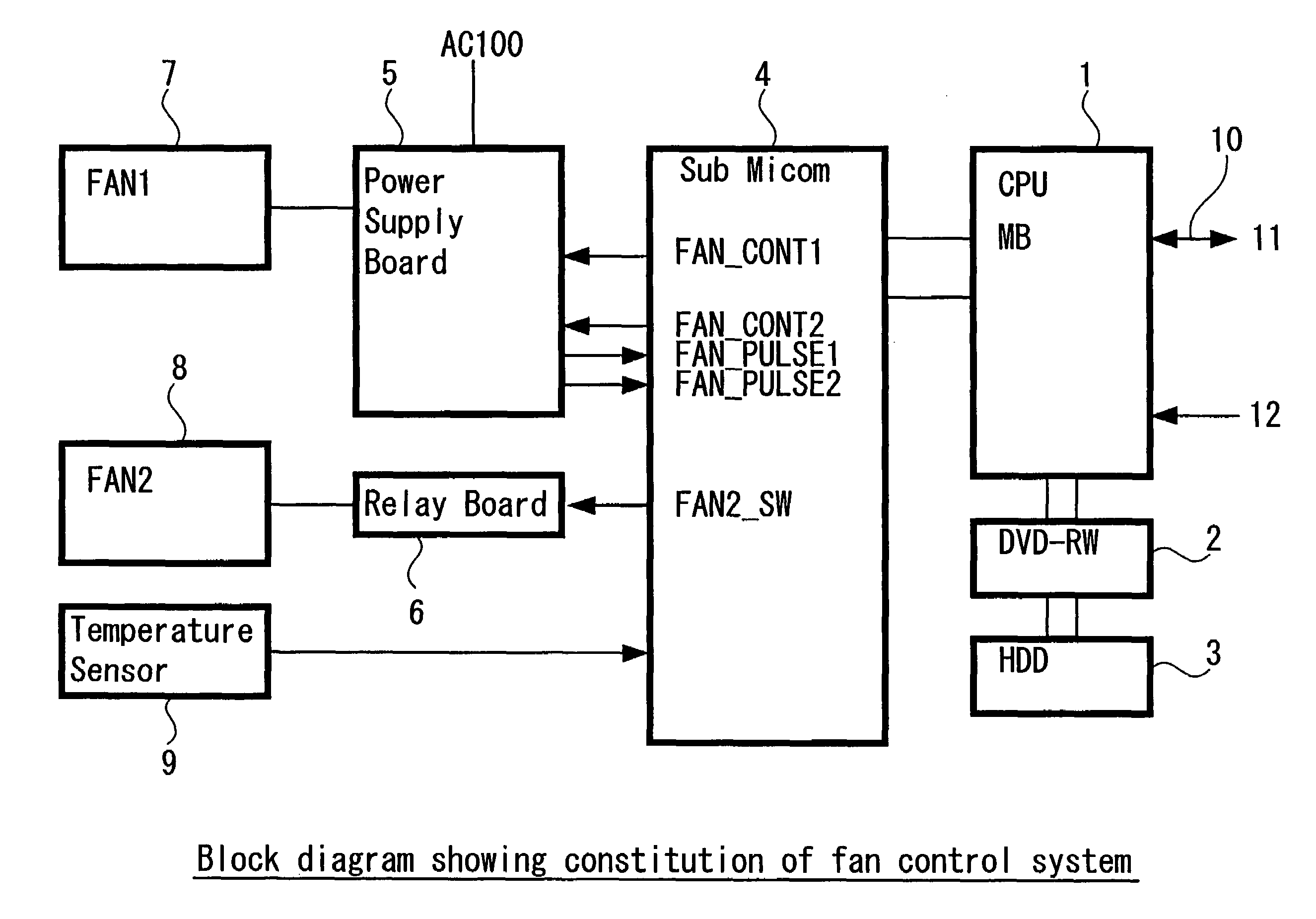
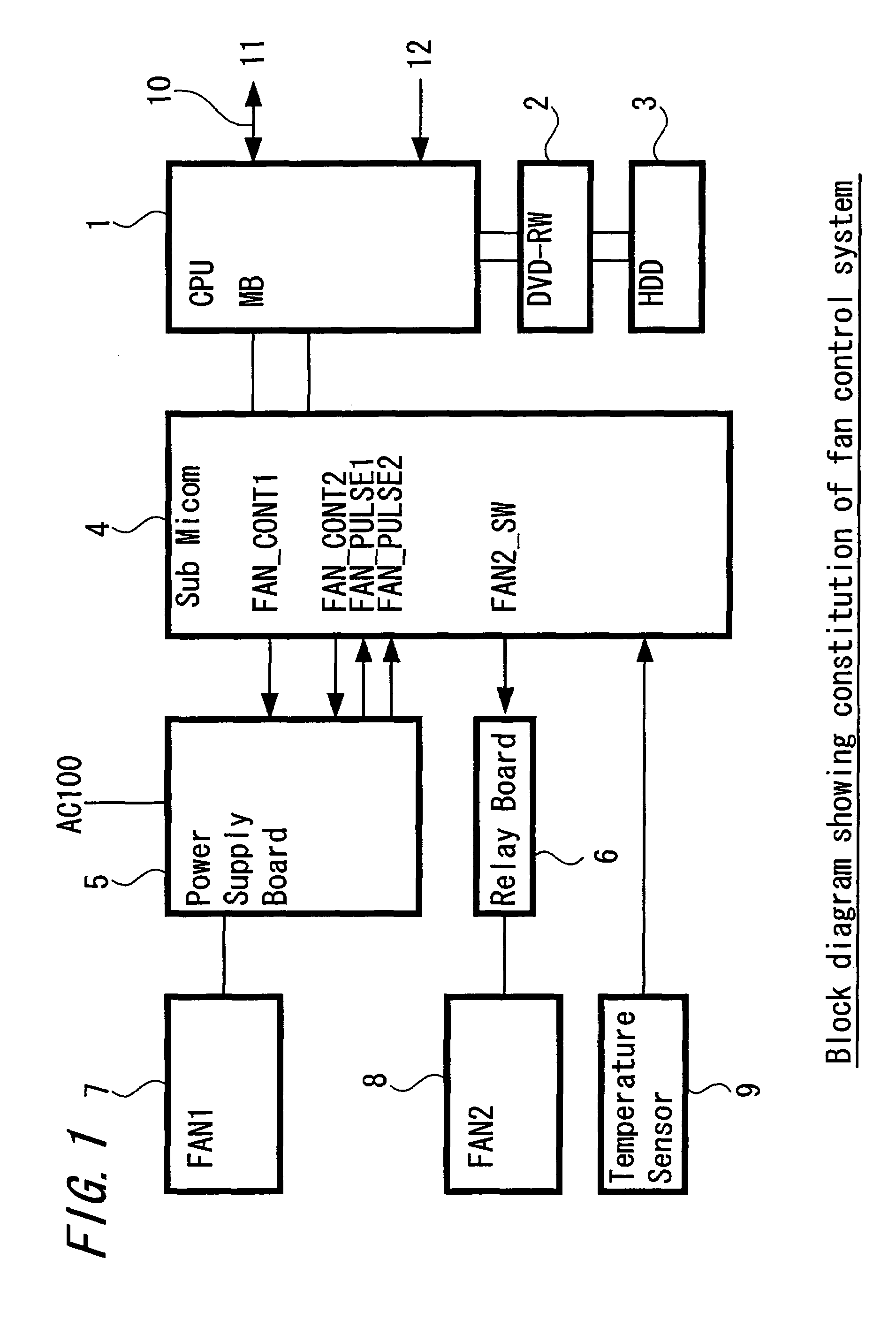
[0038]FIG. 1 is a block diagram showing a constitution of a fan control system applied to an exemplified embodiment according to the present invention.

[0039]In FIG. 1, the fan control system is provided on a main board and is constituted to include a CPU (Central Processing Unit) 1 which controls the operation of the equipment, a reproducible DVD-RW (Digital Versatile DISC Rewritable) 2 which records audio data and video data on a detachable disc type recording medium, and an HDD (Hard Disc Drive) 3 which records program data readably and at the same time records audio data and video data reproducibly on a fixed disc type recording medium.

[0040]The CPU 1 is connected to a server 11 by means of a network 10 and constituted to have a communication function for downloading reservation program information and version upgrade programs, to have a state control functio...


PUM


Abstract

A fan control apparatus and method that sets a stop period constant at a starting time by adding a fan control in a time axis to a fan control by a temperature sensor. The fan control apparatus includes a temperature sensor that detects the temperature in the equipment body; and a CPU and a sub-microcomputer that has a temperature control function, that perform the control of the cooling fans according to the detected temperature value. The CPU performs a communication with a server connected to the equipment body via a network; and the sub-microcomputer performs the control of the cooling fans according to the time value based on the communication commencement.

Description

BACKGROUND OF THE INVENTION[0001]1. Field of the Invention:[0002]The present invention relates to a fan control apparatus and a fan control method, for example, for cooling a heat generating portion in equipment by using a cooling fan.[0003]2. Description of the Related Art:[0004]In a conventional fan control apparatus which cools, for example, a power supply unit or an actuator of heat generating portions by using a cooling fan, the cooling fan is always made rotated when the power supply of the equipment body is turned on.[Patent Document 1][0005]Japanese Laid-open Patent publication No.2001-56724[0006]However, in the above mentioned conventional fan control apparatus, the cooling fan is always rotated whenever the power supply of the equipment body is turned on, so that there was a disadvantage that a rotation noise is always generated caused by the rotation of the cooling fan and the quality of the equipment goes down by the undesired sound in an environment where quietness is r...

Claims


Application Information

Patent Timeline
Patent Type & Authority Patents(United States)
IPC IPC(8): G05D23/32F25D23/12F04D27/02G06F1/18G06F1/20G06F1/32H01L23/467H05K7/20
CPCG06F1/181G06F1/206G06F1/3209H05K7/20727H05K7/20836F04D27/008H01L23/467Y02B60/1275H01L2924/0002H01L2924/00Y02D10/00
Inventor INOUE, KENICHINOTSUYU, TOSHIAKI
Owner SONY CORP
Why Eureka
Try Eureka