Electrical energy capture system with circuitry for blocking flow of undesirable electrical currents therein
What is Al technical title?
Al technical title is built by PatSnap Al team. It summarizes the technical point description of the patent document.
a technology of circuitry and electrical current, applied in the direction of motor/generator/converter stopper, electric device, engine-driven generator, etc., can solve the problems of unsatisfactory attempts to make productive use of such energy, prior art off-highway vehicles typically waste the energy generated from dynamic braking, and waste of electric energy generated in dynamic braking mod
Inactive Publication Date: 2009-08-11
GE GLOBAL SOURCING LLC
View PDF8 Cites 42 Cited by
Summary
Abstract
Description
Claims
Application Information
AI Technical Summary
This helps you quickly interpret patents by identifying the three key elements:
Problems solved by technology
Method used
Benefits of technology
Problems solved by technology
Such electric energy generated in the dynamic braking mode is typically wasted.
As indicated above, prior art Off Highway Vehicles typically waste the energy generated from dynamic braking.
Attempts to make productive use of such energy have been unsatisfactory.
Among the disadvantages of such a system are the safe storage of the hydrogen gas and the need to carry water for the electrolysis process.
Still other prior art systems fail to recapture the dynamic braking energy at all, but rather selectively engage a special generator that operates when the associated vehicle travels downhill.
One of the reasons such a system is unsatisfactory is because it fails to recapture existing braking energy and fails to make the captured energy available for reuse on board the Off Highway Vehicle.
Method used
Image
Click on the blue label to locate the original text in one second.
Reading with bidirectional positioning of images and text.
Examples
Embodiment Construction
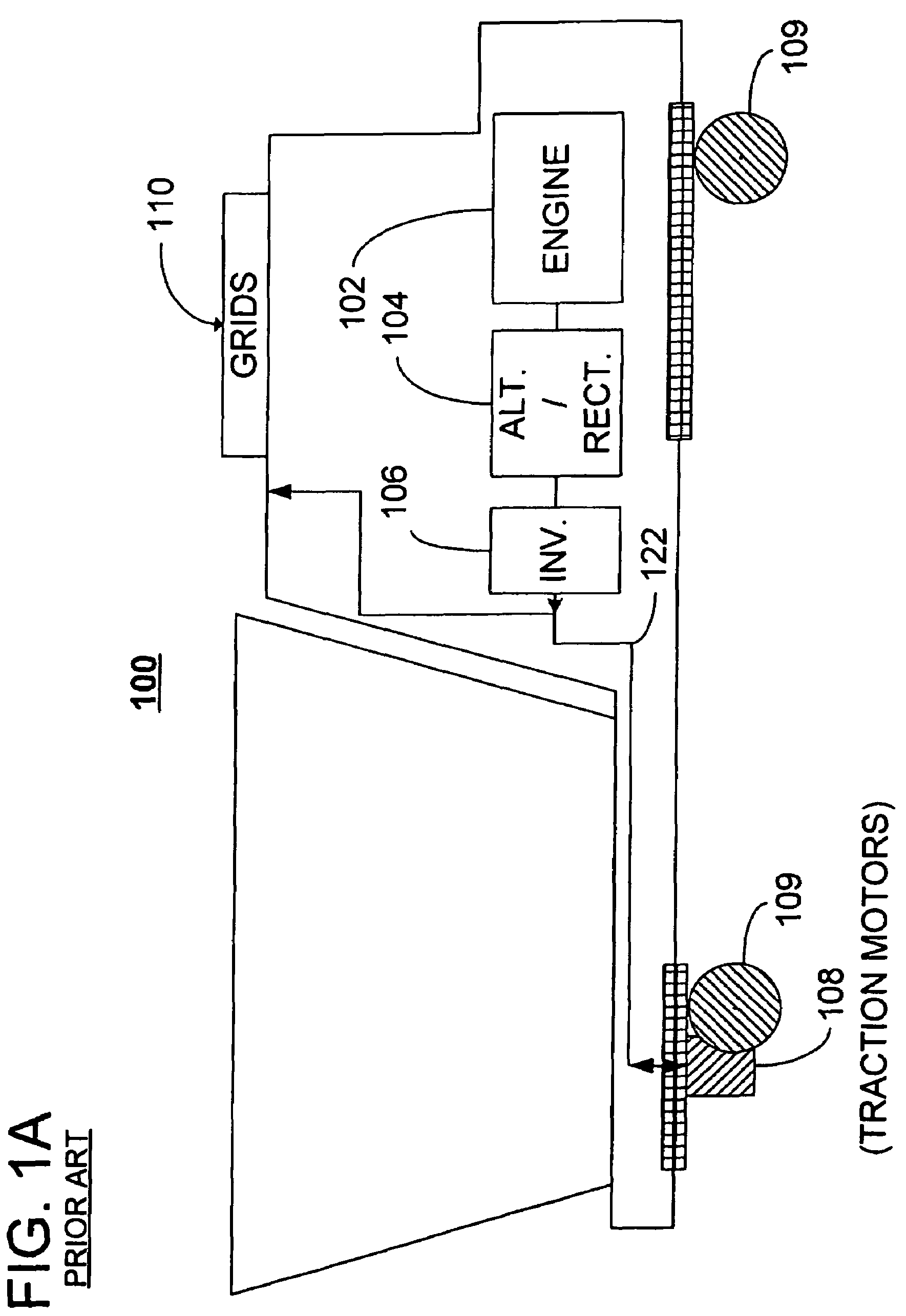
[0038]FIG. 2 is a block diagram of one embodiment of a hybrid energy Off Highway Vehicle system 200. In this embodiment, the hybrid energy Off Highway Vehicle system preferably captures and regenerates at least a portion of the dynamic braking electric energy generated when the vehicle traction motors operate in a dynamic braking mode.
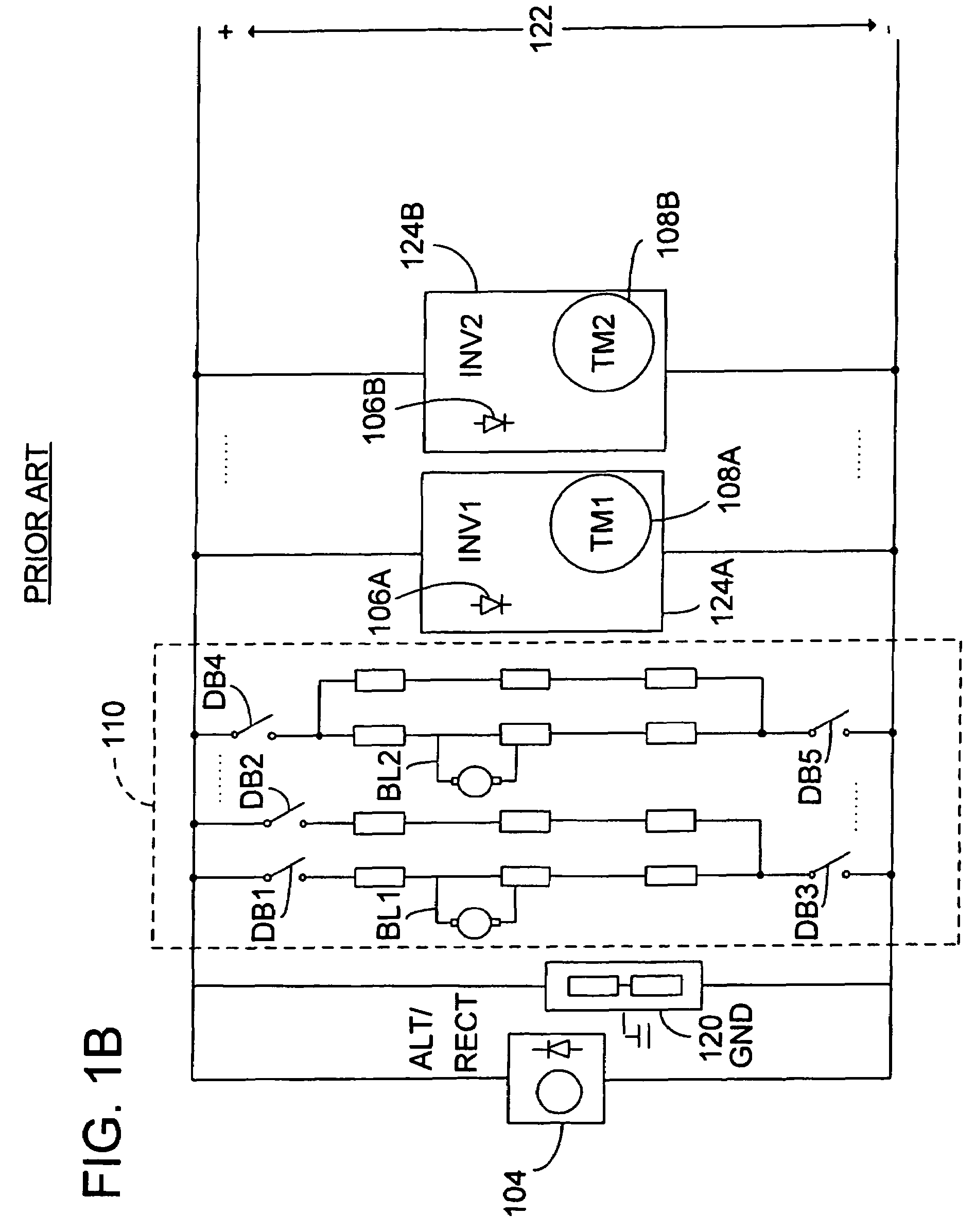
[0039]The Off Highway Vehicle system includes an Off Highway Vehicle 200 having a primary energy source 104. In some embodiments, a power converter is driven by the primary energy source 102 and provides primary electric power. A traction bus 122 is coupled to the power converter and carries the primary electric power. A traction drive 108 is coupled to the traction bus 122. The traction drive 108 has a motoring mode in which the traction drive is responsive to the primary electric power for propelling the Off Highway Vehicle 200. The traction drive 108 has a dynamic braking mode of operation wherein the traction drive generates dynamic braking electri...
PUM
Abstract
An electrical energy capture system, as may be carried on a hybrid energy, electro-motive, self-powered traction vehicle, is provided. The system may be used for storing electrical power generated on the vehicle and for discharging the stored electrical power for use on the vehicle. The system includes circuitry connected to a plurality of electrical energy storage devices connected in parallel circuit to one another. The circuitry may be configured to establish a respective circuit path for charging and discharging electrical energy from each energy storage device with respect to a DC bus. The circuitry is further configured to block a flow of electrical current from any one of the storage devices to any of the other storage devices, thereby avoiding flow of currents that could otherwise circulate among the electrical energy storage devices due to electrical imbalances that may occur in one or more of the electrical energy storage devices.
Description
CROSS REFERENCE TO RELATED APPLICATIONS[0001]The invention of the present application is a Continuation-in-Part of U.S. patent application Ser. No. 10 / 918,849, filed on Aug. 9, 2004, now U.S. Pat. No. 7,137,344, and entitled “HYBRID ENERGY OFF HIGHWAY VEHICLE LOAD CONTROL SYSTEM AND METHOD”, which in turn is a Continuation-in-Part of U.S. patent application Ser. No. 10 / 378,335, filed on Mar. 3, 2003, now U.S. Pat. No. 6,973,880, and entitled “HYBRID ENERGY OFF HIGHWAY VEHICLE ELECTRIC POWER STORAGE SYSTEM AND METHOD”, which in turn is a Continuation-in-Part of U.S. patent application Ser. No. 10 / 033,347, filed on Dec. 26, 2001, entitled “HYBRID ENERGY LOCOMOTIVE ELECTRICAL POWER STORAGE SYSTEM” and now issued as U.S. Pat. No. 6,591,758, which claims priority from U.S. Provisional Application Ser. No. 60 / 278,975, filed on Mar. 27, 2001.[0002]The above-identified patent applications and patents are commonly owned by the assignee of the present invention.[0003]The above-identified pate...
Claims
Application Information
Patent Timeline
Application Date:The date an application was filed.
Publication Date:The date a patent or application was officially published.
First Publication Date:The earliest publication date of a patent with the same application number.
Issue Date:Publication date of the patent grant document.
PCT Entry Date:The Entry date of PCT National Phase.
Estimated Expiry Date:The statutory expiry date of a patent right according to the Patent Law, and it is the longest term of protection that the patent right can achieve without the termination of the patent right due to other reasons(Term extension factor has been taken into account ).
Invalid Date:Actual expiry date is based on effective date or publication date of legal transaction data of invalid patent.