System for thin film deposition utilizing compensating forces

a compensating force and thin film technology, applied in the direction of chemical vapor deposition coating, coating, semiconductor devices, etc., can solve the problems of large amount of chemical vapor deposition reaction, difficult to avoid some direct reaction of different precursors, and relatively insensitive to transport non-uniformities, etc., to achieve the effect of reducing the residence tim

Active Publication Date: 2009-08-11
EASTMAN KODAK CO
View PDF12 Cites 108 Cited by
  • Summary
  • Abstract
  • Description
  • Claims
  • Application Information

AI Technical Summary

Benefits of technology

[0064]It is an advantage of the present invention that it can provide a compact apparatus for atomic layer deposition onto a substrate that is well suited to a number of different types of substrates and deposition environments.
[0065]It is a further advantage of the present invention that it allows operation, in preferred embodiments, under atmospheric pressure conditions.
[0066]It is yet a further advantage of the present invention that it is adaptable for deposition on a web or other moving substrate, including deposition onto a large area substrate.
[0067]It is still a further advantage of the present invention that it can be employed in low temperature processes at atmospheric pressures, which may be practiced in an unsealed environment, open to ambient atmosphere. The method of the present invention allows control of the gas residence time τ in the relationship shown earlier in equation (3), allowing residence time τ to be reduced, with system pressure and volume controlled by a single variable, the gas flow.
[0068]As used herein, the terms “vertical,”“horizontal,”“top,”“bottom,”“front,”“back,” or “parallel,” and the like, unless otherwise indicated, are with reference to a front / bottom horizontal face of the delivery device or a top horizontal parallel surface of the substrate being treated, in an theoretical configuration in which the delivery head is vertically over the substrate, although that configuration is optional, for example, the substrate can be positioned over the face of the delivery head or otherwise positioned.

Problems solved by technology

In practice, in any system it is difficult to avoid some direct reaction of the different precursors leading to a small amount of chemical vapor deposition reaction.
Self-saturating surface reactions make ALD relatively insensitive to transport non-uniformities, which might otherwise impair surface uniformity, due to engineering tolerances and the limitations of the flow system or related to surface topography (that is, deposition into three dimensional, high aspect ratio structures).
As a general rule, a non-uniform flux of chemicals in a reactive process generally results in different completion times over different portions of the surface area.
However, in spite of its inherent technical capabilities and advantages, a number of technical hurdles still remain.
However, it is difficult to obtain a reliable scheme for introducing the needed series of gaseous formulations into a chamber at the needed speeds and without some unwanted mixing.
In a typical ALD chamber, the volume (V) and pressure (P) are dictated independently by the mechanical and pumping constraints, leading to difficulty in precisely controlling the residence time to low values.
Existing ALD approaches have been compromised with the trade-off between the need to shorten reaction times with improved chemical utilization efficiency, and, on the other hand, the need to minimize purge-gas residence and chemical removal times. One approach to overcome the inherent limitations of “pulsed” delivery of gaseous material is to provide each reactant gas continuously and to move the substrate through a region containing each gas in succession.
In these systems, some mechanism must be employed to confine a particular gas to a spatial region in order that the substrate can sample all of the gases during its movement, but the individual mutually reactive gases cannot mix causing undesirable CVD deposition.
While systems such as those described in the '563 Yudovsky and '022 Suntola et al. patents may avoid some of the difficulties inherent to pulsed gas approaches, these systems have other drawbacks.
The complex arrangements of both the gas flow delivery unit of the '563 Yudovsky patent and the gas flow array of the '022 Suntola et al. patent, each providing both gas flow and vacuum, make these solutions difficult to implement, costly to scale, and limit their potential usability to deposition applications onto a moving substrate of limited dimensions.
Moreover, it would be very difficult to maintain a uniform vacuum at different points in an array and to maintain synchronous gas flow and vacuum at complementary pressures, thus compromising the uniformity of gas flux that is provided to the substrate surface.

Method used


Image

  • System for thin film deposition utilizing compensating forces
  • System for thin film deposition utilizing compensating forces
  • System for thin film deposition utilizing compensating forces

Examples


example 1

Comparative

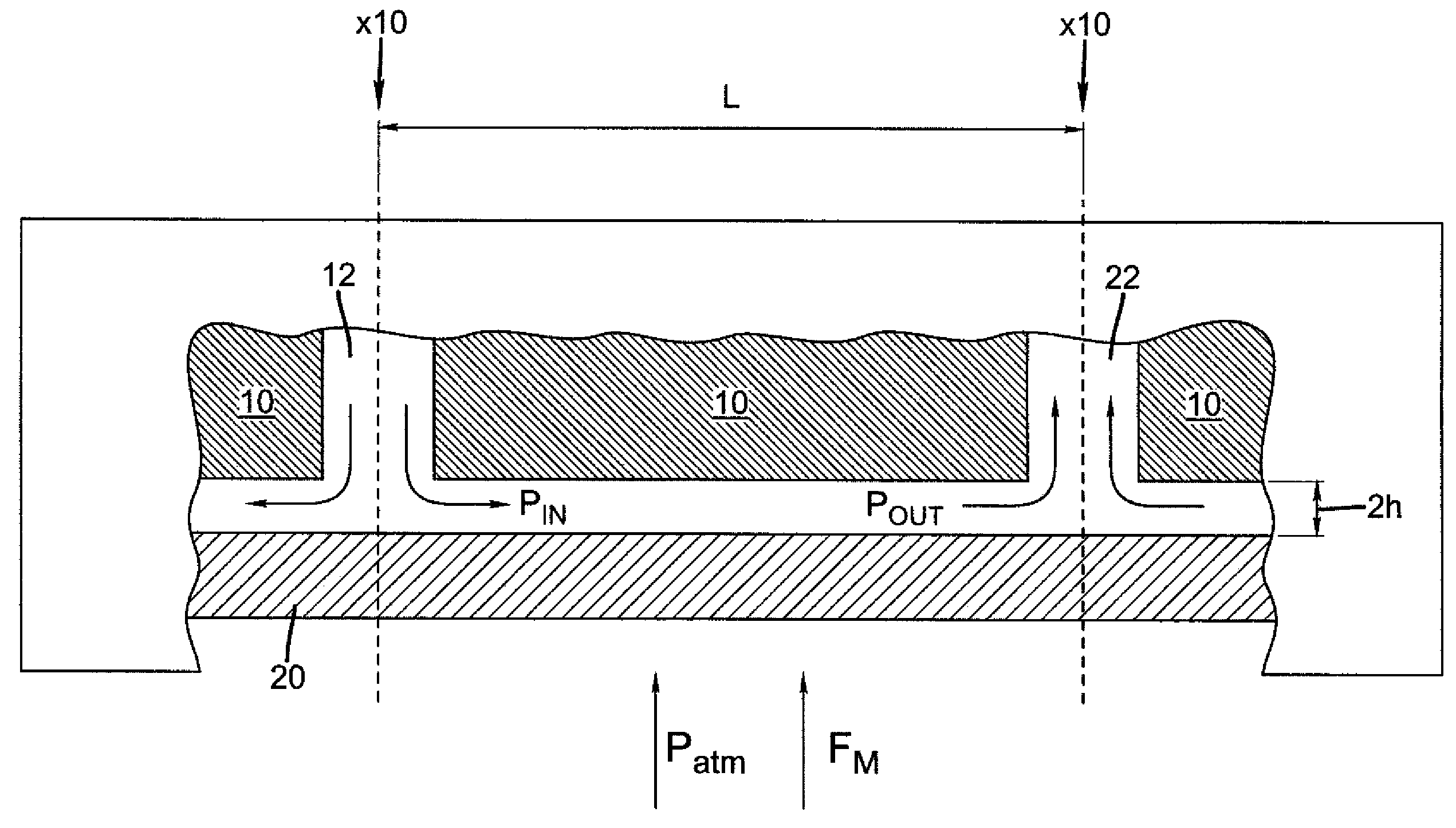
[0244]This example quantifies the forces acting on a substrate when the average exhaust suction is ½ of the weight per unit area of the substrate.

[0245]In this example the substrate rests on top of the deposition head such that the force of gravity acts to pull the substrate toward the deposition head.

[0246]The substrate is a piece of conventional glass with a density of 2.2 g / cm3 and a thickness of 1 mm. Based upon its area the mass of the glass will be 2.2 grams and the substrate weight, thus the gravitational force acting on the substrate, will be 0.0216 N. The weight per unit area of the substrate is therefore 21.6 Pa.

[0247]If the exhaust channel pressure is set at 10.8 Pa (0.043 in H2O) then the exhaust pressure will be ½ of the weight per unit area of the substrate. According to equation (5) the critical force at which the substrate will separate from the head will be 0.0108 N. Since this force is substantially less than the weight of the substrate at 0.0216 N, smal...

example 2

Inventive

[0248]This example quantifies the forces acting on a substrate when the average exhaust suction is 5 times the weight per unit area of the substrate.

[0249]In this example the substrate rests on top of the deposition head such that the force of gravity acts to pull the substrate toward the deposition head.

[0250]The substrate is a piece of conventional glass with a density of 2.2 g / cm3 and a thickness of 1 mm. Based upon its area the mass of the glass will be 2.2 grams and the substrate weight, thus the gravitational force acting on the substrate, will be 0.0216 N. The weight per unit area of the substrate is therefore 21.6 Pa.

[0251]If the exhaust channel pressure is set at 108 Pa (0.43 in H2O) then the exhaust pressure will be 5 times the weight per unit area of the substrate. According to equation (5) the critical force at which the substrate will separate from the head will be 0.108 N. Since this force is substantially more than the weight of the substrate at 0.0216 N, sma...

example 3

Comparative

[0252]This example employs the same configuration as in Example 1 except that the deposition head is inverted with the substrate below the head. Therefore, the force of gravity acts to pull the substrate from the head.

[0253]This example quantifies the forces acting on a substrate when the average exhaust suction is ½ of the weight per unit area of the substrate.

[0254]The substrate is a piece of conventional glass with a density of 2.2 g / cm3 and a thickness of 1 mm. Based upon its area the mass of the glass will be 2.2 grams and the substrate weight, thus the gravitational force acting on the substrate, will be 0.0216 N. The weight per unit area of the substrate is therefore 21.6 Pa.

[0255]If the exhaust channel pressure is set at 10.8 Pa (0.043 in H2O) then the exhaust pressure will be ½ of the weight per unit area of the substrate. According to equation (5) the critical force at which the substrate will separate from the head will be 0.0108 N. Since the gravitational forc...


PUM

PropertyMeasurementUnit
temperatureaaaaaaaaaa
thicknessaaaaaaaaaa
thicknessaaaaaaaaaa

Abstract

A process for depositing a thin film material on a substrate is disclosed, comprising simultaneously directing a series of gas flows from the output face of a delivery head of a thin film deposition system toward the surface of a substrate, and wherein the series of gas flows comprises at least a first reactive gaseous material, an inert purge gas, and a second reactive gaseous material, wherein the first reactive gaseous material is capable of reacting with a substrate surface treated with the second reactive gaseous material. A system capable of carrying out such a process is also disclosed.

Description

CROSS-REFERENCE TO RELATED APPLICATIONS[0001]The present application is related to U.S. application Ser. No. 11 / 392,007, filed Mar. 29, 2006 by Levy and entitled, “PROCESS FOR ATOMIC LAYER DEPOSITION,” U.S. application Ser. No. 11 / 392,006, filed Mar. 29, 2006 by Levy and entitled “APPARATUS FOR ATOMIC LAYER DEPOSITION,” U.S. application Ser. No. 11 / 620,738, filed Jan. 8, 2007, by Levy and entitled “DELIVERY DEVICE FOR DEPOSITION,” U.S. application Ser. No. 11 / 620,740, filed Jan. 8, 2007 by Nelson et al. and entitled “DELIVERY DEVICE COMPRISING GAS DIFFUSER FOR THIN FILM DEPOSITION,” U.S. application Ser. No. 11 / 620,744, filed Jan. 8, 2007 by Levy and entitled, “DEPOSITION SYSTEM AND METHOD USING A DELIVERY HEAD SEPARATED FROM A SUBSTRATE BY GAS PRESSURE,” U.S. application Ser. No. 11 / 861,420 filed Sep. 26, 2007 by Kerr et al. and entitled, “DEPOSITION SYSTEM FOR THIN FILM FORMATION,” U.S. application Ser. No. 11 / 861,402 filed Sep. 26, 2007 by Kerr et al. and entitled “DELIVERY DEVIC...

Claims


Application Information

Patent Timeline
Patent Type & Authority Patents(United States)
IPC IPC(8): H01L21/84H01L21/00H01L21/311H01L21/461
CPCC23C16/45551H01L29/4908C23C16/458Y10S438/908B33Y80/00
Inventor LEVY, DAVID H.KERR, ROGER S.CAREY, JEFFREY T.
Owner EASTMAN KODAK CO
Why Eureka
Try Eureka