Method of manufacturing and stacking packaging units with increased stability

a packaging unit and stability technology, applied in the field of beverage bottling plants, can solve the problems of unstable or at least completely stable stacking of these packaging units, stacks are very unstable or at least not very stable, and the stack is not stable or at least stable. stable or at least completely stable stacking, the effect of increasing the stability of the stack of packaging units

Inactive Publication Date: 2009-08-18
KHS MASCHEN UND ANALAGENBAU AKTIENGES
View PDF16 Cites 8 Cited by
  • Summary
  • Abstract
  • Description
  • Claims
  • Application Information

AI Technical Summary

Benefits of technology

[0016]As a result of this mating or interlocking relationship of the packaging units, the stability of the stack of packaging units is increased as a result of the fact that it prevents or essentially prevents the lateral slippage of the individual packaging units in the stack of packaging units or at least makes such slippage more difficult.
[0017]As a result of at least one possible configuration of the packaging units and / or by the possible interlocking of the bundles, the height of the stack of packaging units is reduced or essentially reduced, which further contributes to the stability of the stack of packaging units and / or makes it possible with a specified maximum height of the stack of packaging units to possibly increase the number of packaging units in the stack.
[0018]As a result of the interlocking of the packaging units, the containers are protected or essentially protected from damage in the vicinity of their neck and mouth.
[0019]With an appropriate or desired realization of the tray openings in terms of size and / or shape, it is also possible to create conditions in which the forces of gravity in the stack of packaging units are not exerted or essentially not exerted on the mouths of the containers or the closures that are located on the mouths of the containers but, for example, possibly on the shoulder area that is adjacent or essentially adjacent the mouth of each container and widens toward the bottom of the container and / or possibly on a flange or even a collar that is provided on the container, as a result of which the load or the risk of damage to individual containers in the stack of packaging units is reduced or essentially reduced.

Problems solved by technology

One possible disadvantage with these packaging units, and with the shrinktrays and / or shrinkpads mentioned above, is that a stable or at least a completely stable stacking of these packaging units is not possible or at least not always possible, e.g. on palettes for transport and / or storage, especially in high stacks of packaging units.
On the contrary, when the packaging units of the type mentioned above are set on top of one another, the resulting stacks are very unstable or at least not very stable.

Method used


Image

  • Method of manufacturing and stacking packaging units with increased stability
  • Method of manufacturing and stacking packaging units with increased stability
  • Method of manufacturing and stacking packaging units with increased stability

Examples


Embodiment Construction

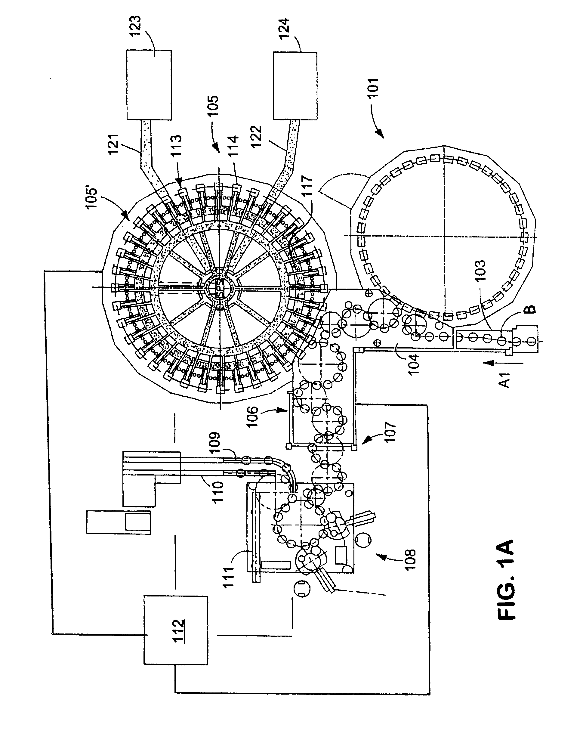
[0031]FIG. 1A shows schematically the main components of one possible embodiment example of a system for filling containers, specifically, a beverage bottling plant for filling bottles B with at least one liquid beverage, in accordance with at least one possible embodiment, in which system or plant could possibly be utilized at least one aspect, or several aspects, of the embodiments disclosed herein.

[0032]FIG. 1A shows a rinsing arrangement or rinsing station 101, to which the containers, namely bottles B, are fed in the direction of travel as indicated by the arrow A1, by a first conveyer arrangement 103, which can be a linear conveyor or a combination of a linear conveyor and a starwheel. Downstream of the rinsing arrangement or rinsing station 101, in the direction of travel as indicated by the arrow A1, the rinsed bottles B are transported to a beverage filling machine 105 by a second conveyer arrangement 104 that is formed, for example, by one or more starwheels that introduce...


PUM

PropertyMeasurementUnit
volumeaaaaaaaaaa
stabilityaaaaaaaaaa
diameteraaaaaaaaaa

Abstract

A beverage bottling plant for filling beverage bottles with a liquid beverage material with a packing apparatus for packing filled bottles and a method of operation thereof. Further, a method of manufacturing and stacking packaging units with increased stability is performed.

Description

BACKGROUND[0001]1. Technical Field[0002]This application relates to a beverage bottling plant for filling beverage bottles with a liquid beverage material with packing apparatus for packing filled bottles and a method of operation thereof.[0003]2. Background Information[0004]A beverage bottling plant for filling bottles with a liquid beverage filling material can possibly comprise a beverage filling machine, which is often a rotary filling machine, with a plurality of beverage filling positions, each beverage filling position having a beverage filling device for filling bottles with liquid beverage filling material. The filling devices may have an apparatus designed to introduce a predetermined volume of liquid beverage filling material into the interior of bottles to a substantially predetermined level of liquid beverage filling material.[0005]Some beverage bottling plants may possibly comprise filling arrangements that receive a liquid beverage material from a toroidal or annular ...

Claims


Application Information

Patent Timeline
Patent Type & Authority Patents(United States)
IPC IPC(8): B65B53/00B65B21/24
CPCB65B21/245B65D71/70B65D71/066B65B61/02
Inventor KOSTER, CHRISTOPHDUPPER, JOSEFBRUKER, ALEXANDERWILZECK, REINHARDJORISSEN, MICHAEL
Owner KHS MASCHEN UND ANALAGENBAU AKTIENGES
Why Eureka
Try Eureka