Leak detection and control

a technology of leak detection and control, applied in the direction of measuring devices, structural/machine measurement, instruments, etc., can solve the problems of structural failure, unnecessarily high bills, and devastating problems of leakage pipes

Inactive Publication Date: 2009-08-18
MICHIGAN AGUA TECH
View PDF18 Cites 66 Cited by
  • Summary
  • Abstract
  • Description
  • Claims
  • Application Information

AI Technical Summary

Benefits of technology

[0005]It would be desirable to ameliorate if not solve completely problems in the art. It would be desirable as well to improve upon the disclosures and approaches of the prior art.
[0006]The present invention provides, in one aspect, a leak detection apparatus for detecting and controlling a leak in a pressurized piping system, which comprises control logic; at least one of a flow detector in communication with said logic, and a pressure detector in communication with said logic; and a control valve in communication with said logic—wherein at least one of the following features is also provided: the flow detector and the pressure detector are both present, with the flow detector present as a single unit, and the pressure detector present as a single unit; the control logic, the at least one of a flow detector and a pressure detector, and the control valve are in close proximity to one another; and the control valve has a baseline condition of being shut off. The apparatus can be construed to be by itself and suitable for application with, or to be otherwise a part of, a system for detecting a leak in a pressurized piping system, especially one having a main fluid supply line and a plurality of branch fluid supply lines in communication with the main fluid supply line. Provided also, in another aspect, is a method for detecting a leak in a pressurized piping system, which beneficially has the main fluid supply line and plurality of branch fluid supply lines in communication with the main line, which can comprise operation of an apparatus or system of the invention, but which, in general, employs pressure decay and / or flow properties to ascertain whether or not a leak is present, and, preferably also to control a leak that has been detected hereby.
[0007]The invention is useful in leak detection and control.

Problems solved by technology

Leaking pipes can be a devastating problem.
For example, leaks from water pipes in residential, commercial or institutional type buildings can cause water damage, which is cosmetic or structural in nature; electric failures and fires; and, in freezing weather, ice build up, which can cause structural failure.
A particularly worrisome condition, especially in those structures in which some sort of leak control system is installed, is that in which an electrical supply failure and leaking pipes occur simultaneously.
Then, too, leaking water pipes cause unnecessarily high bills.
Prior art approaches generally were insufficiently reliable, unable to discriminate between controlled and uncontrolled pressure drop at very low flow rates, or too complex or expensive to be effectively utilized in many applications.

Method used


Image

  • Leak detection and control
  • Leak detection and control
  • Leak detection and control

Examples


Embodiment Construction

[0010]The drawings form part of the specification hereof. With respect to the drawings, which are not necessarily drawn to scale, the following is briefly noted:

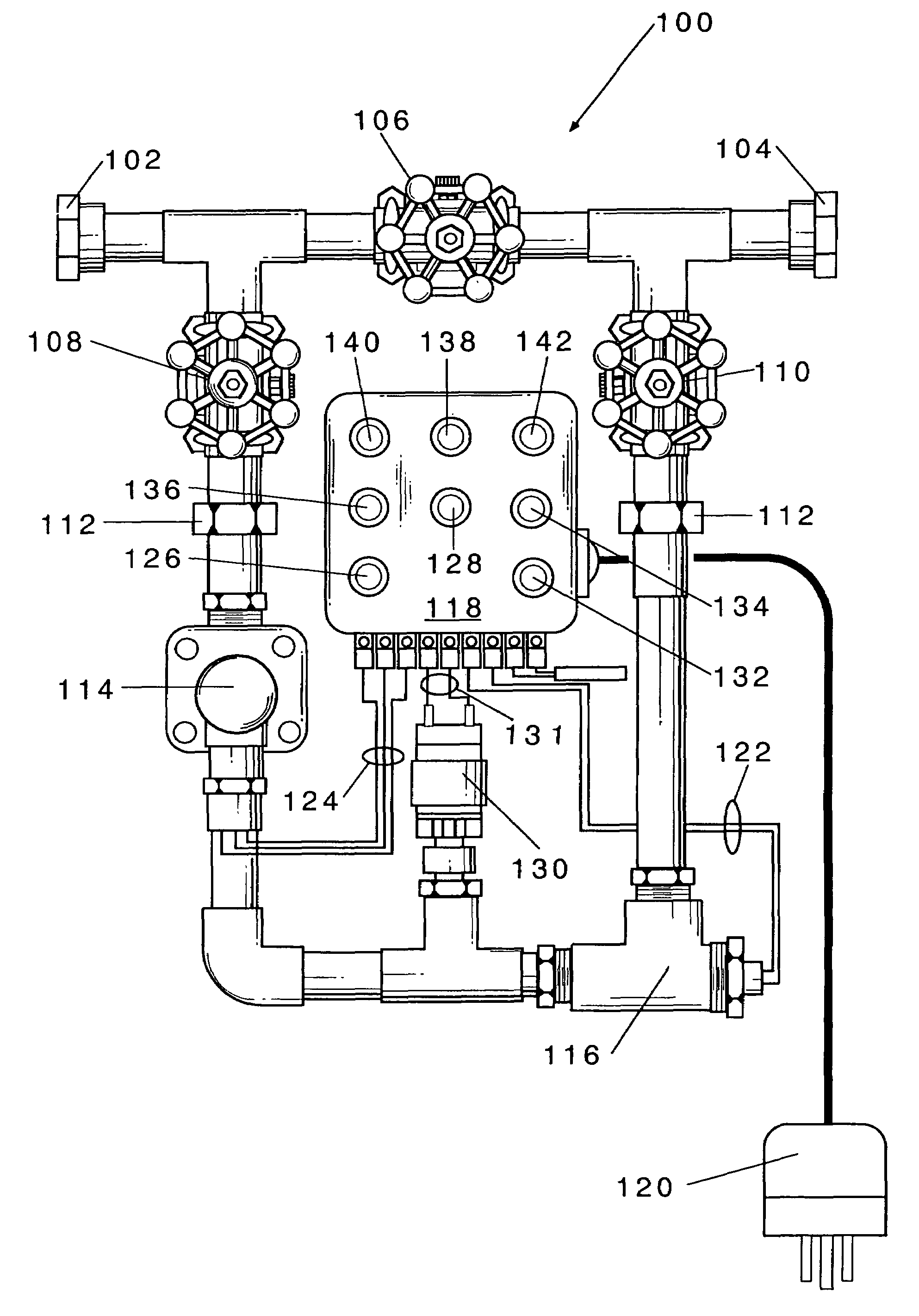
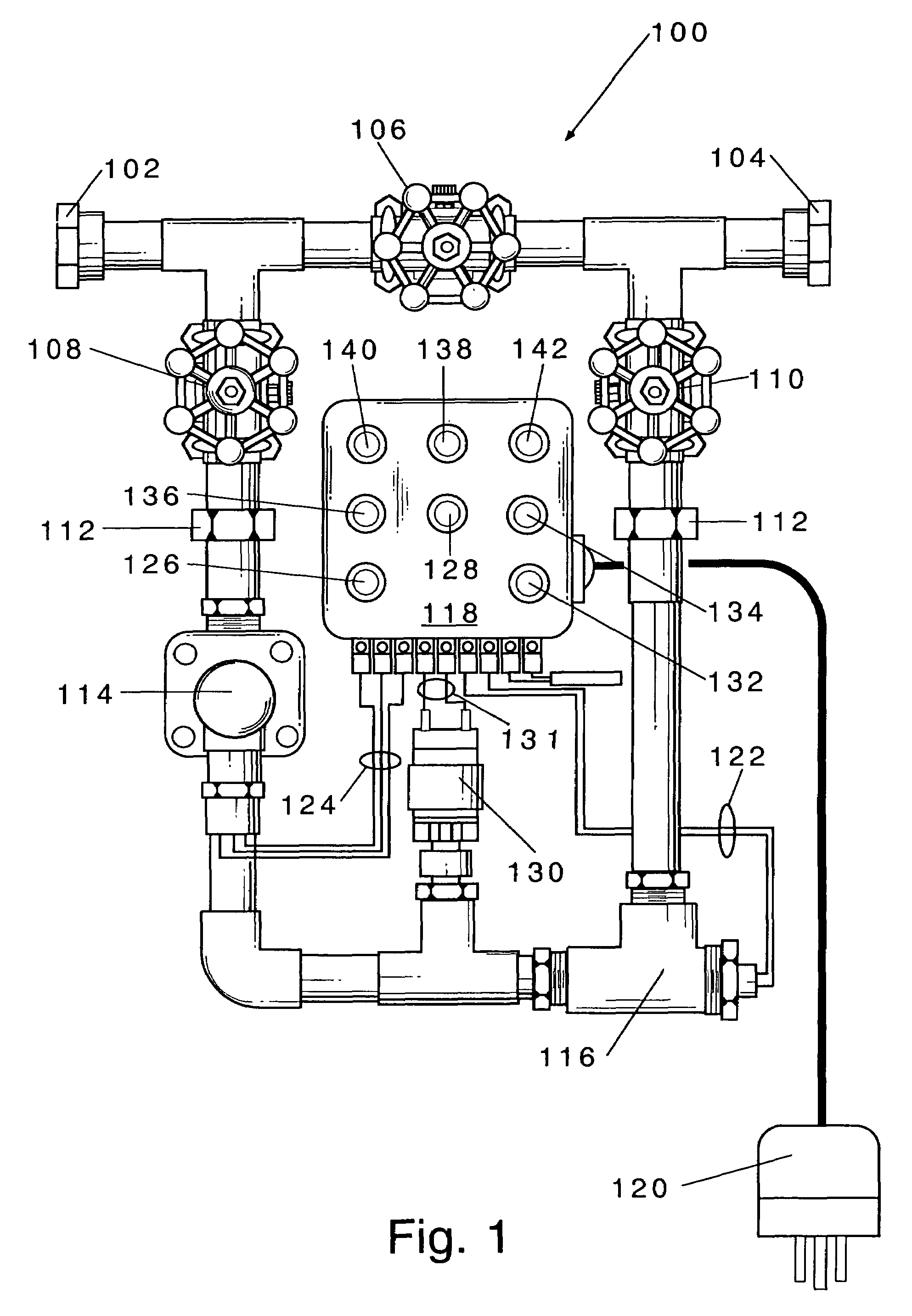
[0011]FIG. 1 shows an embodiment of a leak detection apparatus or system of the invention. Note, the parent application.

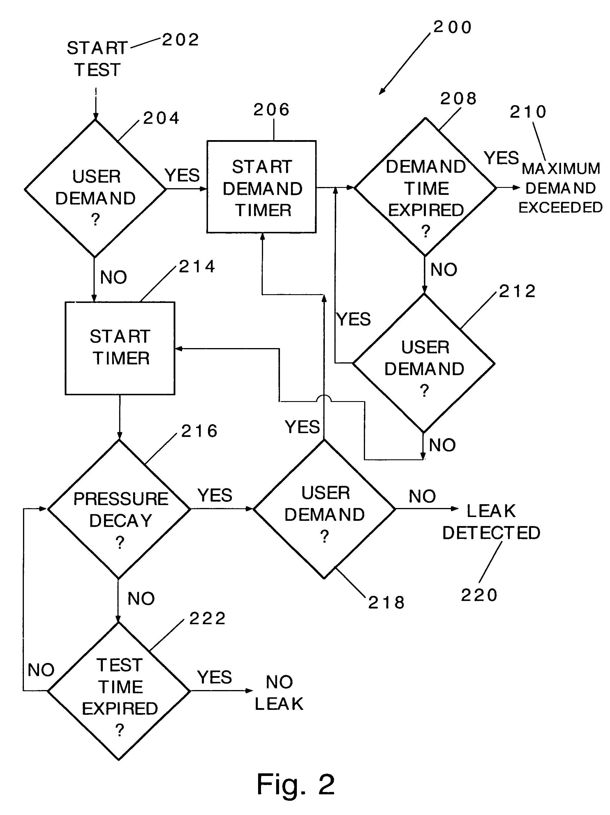
[0012]FIG. 2 shows a flow chart that illustrates an example of a method of the invention. Note, the parent application.

[0013]FIG. 3 shows a front view of another embodiment hereof.

[0014]FIG. 4 shows a plan view of the embodiment of FIG. 3, with its front cover removed.

[0015]FIG. 5 shows a circuit diagram for control logic in a control panel within the embodiment of FIGS. 3 and 4.

[0016]FIG. 6 shows a remote control device that can be employed in conjunction with apparatus of the invention, especially an embodiment such as that of FIGS. 3-5, with a plan of its interaction with that apparatus via its control panel (CP-1).

[0017]FIG. 7 shows a flow chart illustrating operation of the invention with the apparatus...


PUM


Abstract

Fluid leaks can be detected and controlled in a pressurized piping system. Apparatus for this includes control logic; in communication with the logic, a flow detector and/or a pressure detector, and a control valve. One or more of the following is or are provided also: the flow and pressure detectors are both present, and both as single units; the control logic, the flow and/or pressure detector(s) and the control valve are in close proximity to one another; and the control valve has a baseline condition of being shut off. A remote control device can remotely interact with the control logic. Pressure decay and/or flow properties can be employed. The fluid can be water as, for example, in a residential, commercial or institutional system.

Description

[0001]This is a continuation-in-part of U.S. patent application Ser. No. 10 / 665,921 filed on Sep. 18, 2003 A.D., which published as Pub. No. US 2005 / 0072214 A1 on Apr. 7, 2005 A.D., and which issued as U.S. Pat. No. 7,174,771 B2 on Feb. 13, 2007 A.D. The entire specifications to include drawings of that regular utility patent application and that patent application publication are incorporated herein by reference.FIELD AND PURVIEW OF THE INVENTION[0002]In general, the present invention concerns detection and control of leaks in pressurized liquid piping systems, with apparatus and method of its employment. More particularly, the invention concerns a leak detection apparatus and method, in which pressure decay and / or flow properties can be employed to ascertain whether or not a leak is present, and, preferably, to control flow of the liquid. In particular embodiments, devices for measuring pressure decay and flow properties are singular in number and / or are contained within a relativ...

Claims


Application Information

Patent Timeline
Patent Type & Authority Patents(United States)
IPC IPC(8): G01M3/28
CPCG01M3/2815
Inventor COOPER, RALPH W.
Owner MICHIGAN AGUA TECH
Why Eureka
Try Eureka