Actuator for electrical nail gun

a technology of actuator and nail gun, which is applied in the field of actuator, can solve the problems of complicated structure of dc motor, flywheel, belt or gear, and the disadvantage of the actuator of the flywheel, and achieve the effect of simplifying the complicated configuration of the actuator

Active Publication Date: 2009-08-18
ROBERT BOSCH TOOL +1
View PDF18 Cites 43 Cited by
  • Summary
  • Abstract
  • Description
  • Claims
  • Application Information

AI Technical Summary

Benefits of technology

[0005]To overcome the problems as the prior art described above, what is needed, therefore, is to provide an actuator which is arranged in the kinetic energy clutch mechanism of an electrical nail gun, and without using belt, gear or the like, for simplifying the complicated configuration of the actuator.
[0007]According to the present invention, a flywheel is mounted to the outer wall of the motor, and therefore the flywheel is directly driven by the motor. The complicated construction of the actuator is simplified. Thus, it is useful for the miniaturization of the electrical nail gun, and it is an advantage to improve service life and stability of the electrical nail gun.

Problems solved by technology

However, the structure of the DC motor, the flywheel, and the belt or the gears are complicated, and it is a disadvantage to miniaturize the electrical nail gun and improve the service life of the nail gun.
However, the disadvantage consists in the actuator of the flywheel.
This actuator component of the belt or the gears is complicated, and needs to be improved.

Method used


Image

  • Actuator for electrical nail gun
  • Actuator for electrical nail gun
  • Actuator for electrical nail gun

Examples


Embodiment Construction

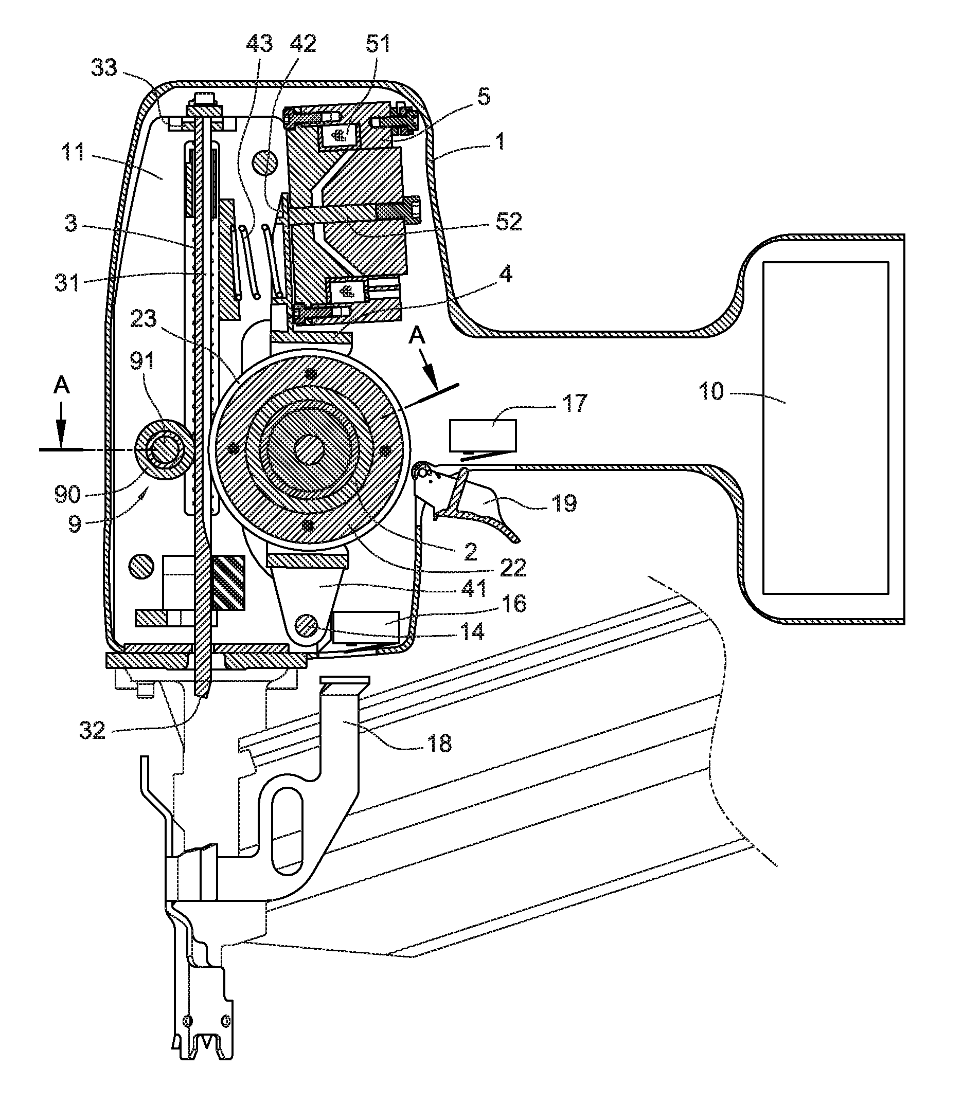
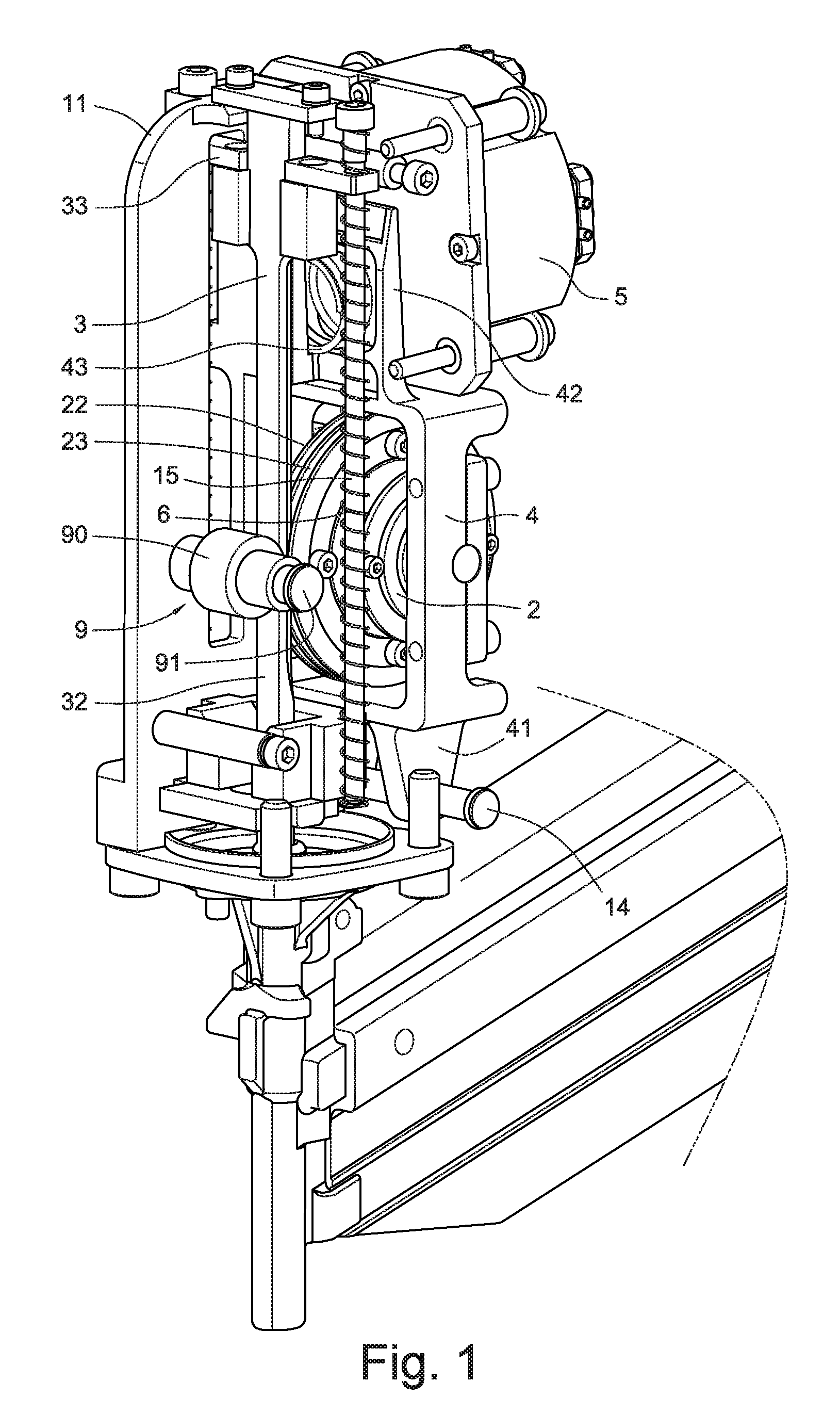
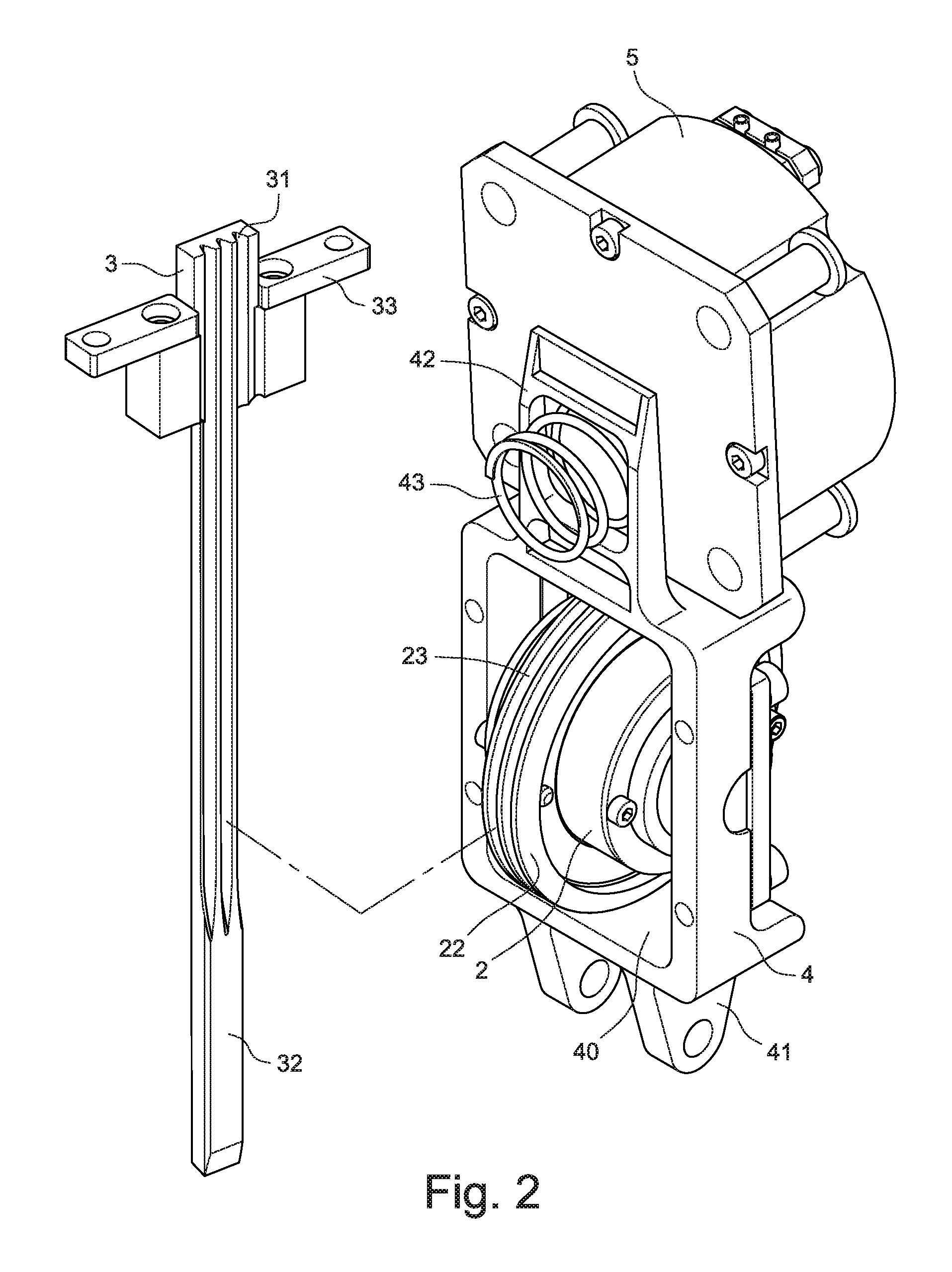
[0017]Referring to FIG. 1 and FIG. 2, a clutch mechanism for transmission of kinetic energy in an electrical nail gun in accordance with a preferred embodiment of the present invention is shown. Referring also to FIG. 3, a cross-sectional view of an actuator of the electrical nail gun in accordance with a preferred embodiment of the present invention is shown. A housing 1 of the electrical nail gun has a battery pack 10 arranged in a distal end thereof for providing DC (direct current) power source. A supporting bracket 11 is formed on a head portion of the housing 1 for mounting a sliding base 3, a swing base 4 and an electric driver 5 thereon. An external-running DC brushless motor 2 is attached to the swing base 4. A first switch 16 and a second switch 17 are arranged in the housing 1. The first switch 16 is located on a bottom end of the housing 1 where a safety sliding rod 18 is capable of touching the first switch 16. The second switch 17 is located on an end side of the housi...


PUM

PropertyMeasurementUnit
electrical poweraaaaaaaaaa
stabilityaaaaaaaaaa
currentaaaaaaaaaa

Abstract

An actuator is arranged in a housing of an electrical nail gun. The actuator includes a sliding base, an external-running brushless direct current motor, a swing base and an electric driver. The sliding base is slidably disposed on an end of a located supporter which is positioned in the housing. The sliding base loads a spring and forms a hitting nail bar thereon. The motor has a stator and a rotator attached on an outer wall of the stator. A flywheel is driven by the motor and is configured to engage or disengage with / from the sliding base. The swing base is pivotally mounted on the housing. The swing base is adjacent to the sliding base and the supporter. The motor is installed in the swing base. The electric driver is attached to the housing and is adjacent to an end side of the swing base. The electric driver has a rod member driven by electricity. The rod member drives the swing base to swing to a first position where the flywheel meshes with the sliding base to thereby drive the sliding base to move downwards, and a second position where the flywheel disengages from the sliding base to thereby cause the sliding base to reposit. It is advantage to simplify the configuration of the actuator for the flywheel and is useful for the miniaturization of the electrical nail gun.

Description

BACKGROUND[0001]The present invention relates to an electrical nail gun with a kinetic energy clutch mechanism, and more particularly to an actuator which is arranged in the kinetic energy clutch mechanism for providing kinetic energy.[0002]An electrical nail gun is a type of tool used to hit nails into wood or some other kind of material. Usually, there is a battery pack or an AC electrical power source in a housing of the electrical nail gun to provide electrical power to a motor, thereby rotating the motor. A rotary kinetic energy of the motor is transformed into a linear kinetic energy by a transmission mechanism to drive a hitting nail bar to hit nails.[0003]Among a more advanced technology, many U.S. patents, such as U.S. Pat. No. 6,607,111 and U.S. Pat. No. 6,669,072 and so on, teach a flywheel driven by a DC motor via a conveyor belt or an engagement of gears, and a clutch assembly being capable of linear movement by traction of a wire disposed on an axis of a solenoid. The ...

Claims


Application Information

Patent Timeline
Patent Type & Authority Patents(United States)
IPC IPC(8): B25C5/15
CPCB25C1/06
Inventor LIANG, CHIA-SHENGTSENG, CHU HSIANG
Owner ROBERT BOSCH TOOL
Why Eureka
Try Eureka