Air conditioning system for motor vehicle

a technology for air conditioning systems and motor vehicles, which is applied in the direction of process and machine control, lighting and heating apparatus, instruments, etc., can solve the problems of insufficient comfort for passengers in the above conventional system, the electronic control unit controlling the target blowing air temperature is reduced, and the temperature of clothing is increased

Inactive Publication Date: 2009-08-25
DENSO CORP
View PDF5 Cites 28 Cited by
  • Summary
  • Abstract
  • Description
  • Claims
  • Application Information

AI Technical Summary

Benefits of technology

[0009]It is, therefore, an object of the present invention, in view of the above mentioned problems, to provide an air conditioning system for a motor vehicle, in which a no-contact temperature sensor is used and which can sufficiently give comfortable feeling to passengers by air-conditioned air even in a time period shortly after the passenger gets into the motor vehicle.
[0011]When calculating the target temperature, in particular, in the case that the passenger gets into the vehicle in the summer or in the winter season, a change of the detected temperature of the passenger's clothing is used for calculating the target temperature, in such a manner that the change of detected temperature is reflected in the target temperature with a time delay, so that a more comfortable feeling can be given to the passenger.
[0013]According to a further feature of the present invention, the electronic control unit calculates the target temperature and changes it to a higher value than a normal value, during a predetermined time period, when the passenger gets into the vehicle during the winter season. As a result, a more comfortable feeling can be given to the passenger, even shortly after the passenger gets into the vehicle.
[0014]On the other hand, the electronic control unit calculates the target temperature and changes it to a lower value than a normal value, during a predetermined time period, when the passenger gets into the vehicle during the summer season. As a result, a more comfortable feeling can be given to the passenger, even shortly after the passenger gets into the vehicle.
[0016]As a result, the power of the air conditioning operation during the predetermined period after the passenger has got into the vehicle is increased compared with the air conditioning operation before the passenger has got into the vehicle, so that a more comfortable feeling can be given to the passenger, even shortly after the passenger has got into the vehicle.

Problems solved by technology

However, the target blowing air temperature is decreased by the electronic control unit within a short period, because heat capacity of the clothing is generally small and thereby the temperature of the clothing is increased in the short period due to the inside temperature of the passenger compartment.
As a result, the above conventional system can not sufficiently give a comfortable feeling to the passenger by the warm air, during a period shortly after the passenger gets into the motor vehicle.
As a result, the above conventional system can not sufficiently give a comfortable feeling to the passenger by the cool air, either, during a period shortly after the passenger gets into the motor vehicle.

Method used


Image

  • Air conditioning system for motor vehicle
  • Air conditioning system for motor vehicle
  • Air conditioning system for motor vehicle

Examples


first embodiment

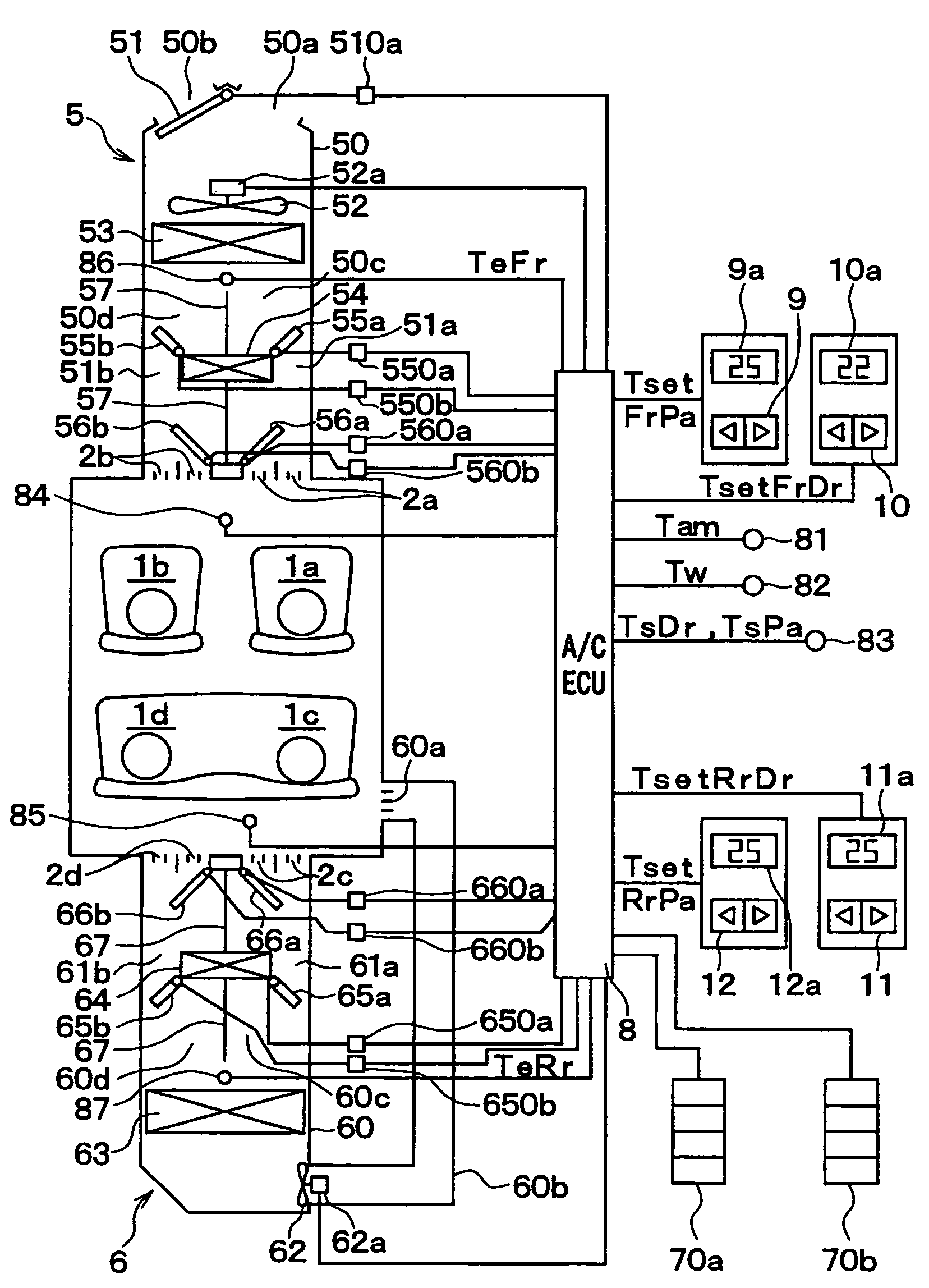
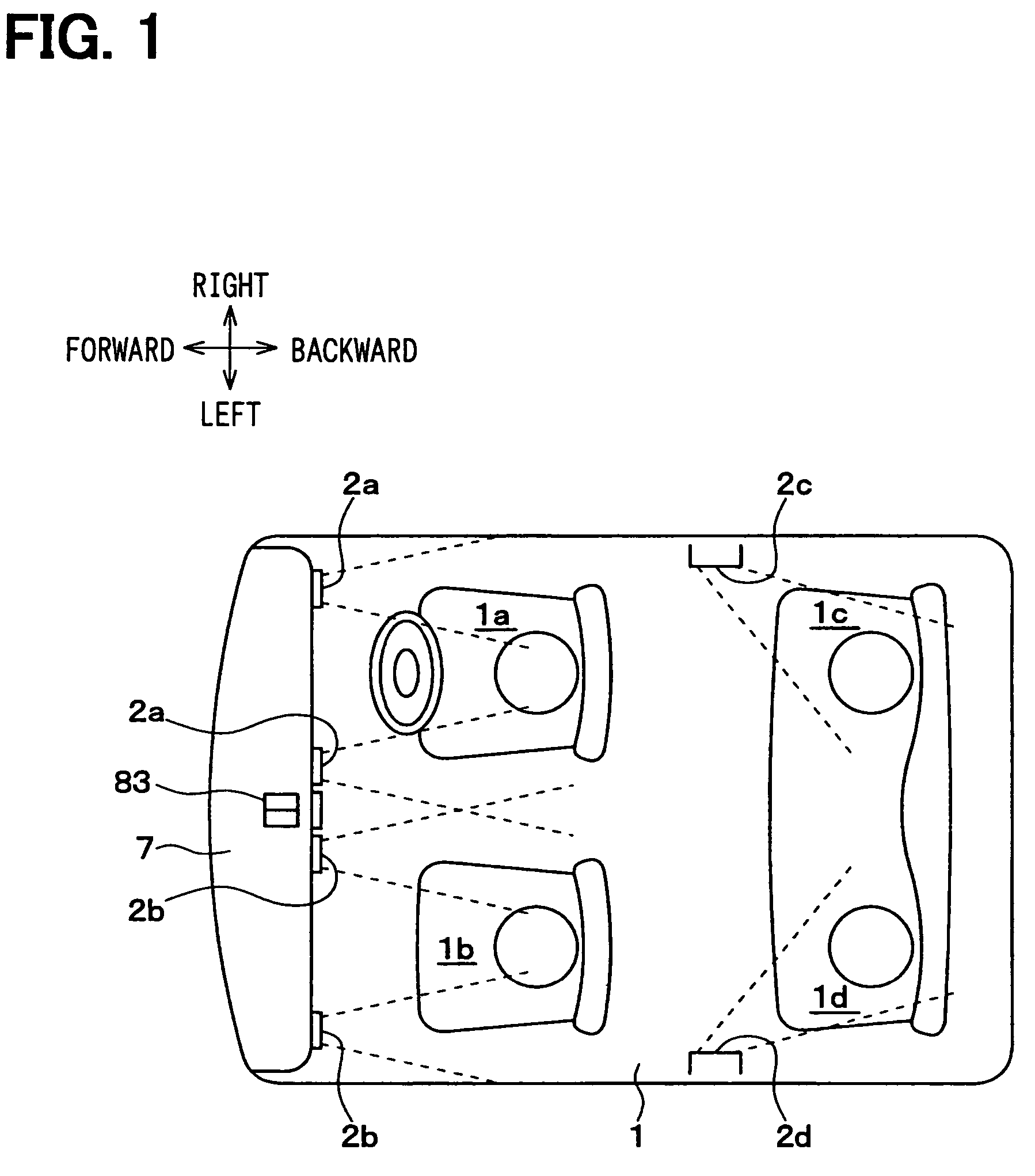
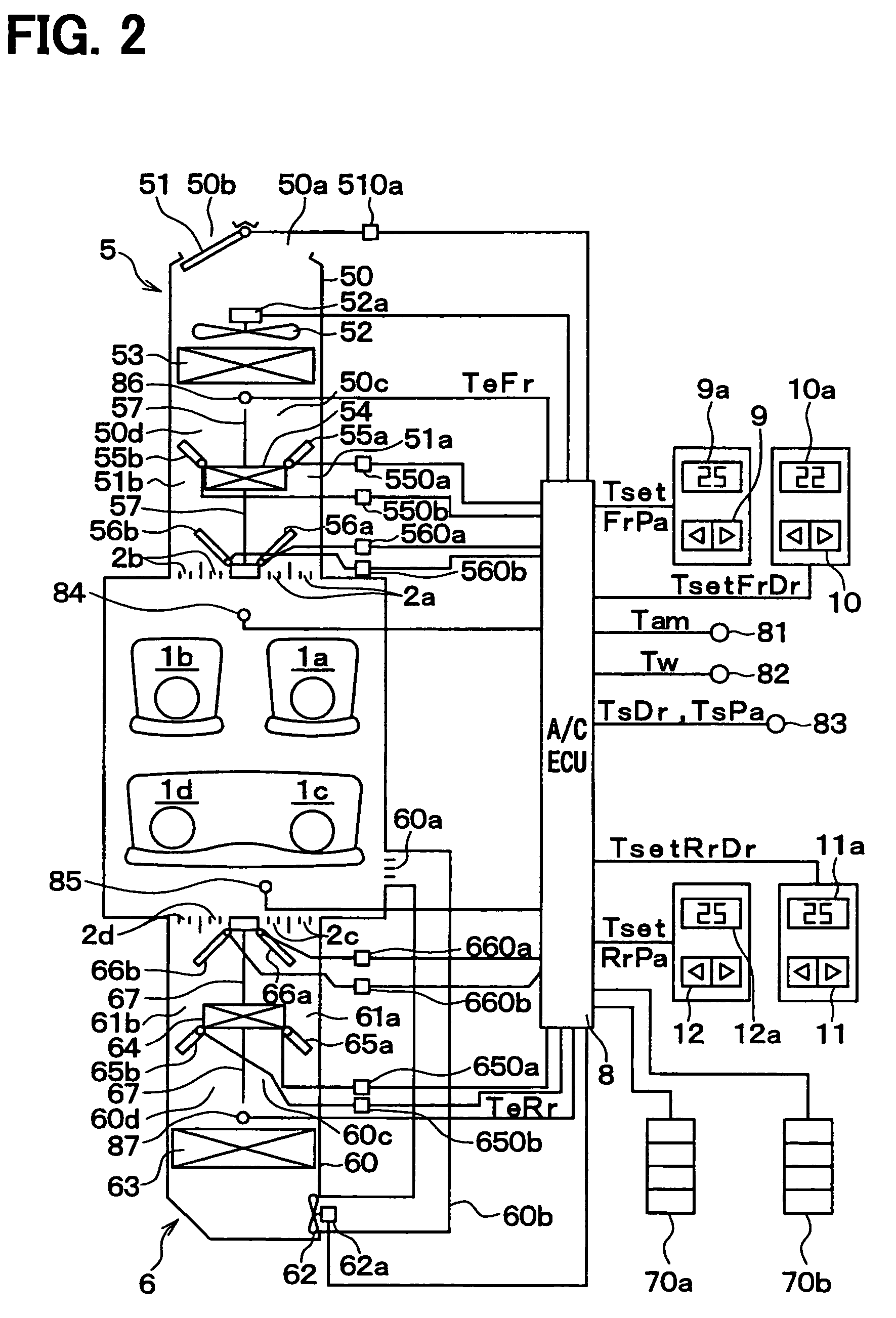
[0043]A first embodiment of the present invention will now be explained with reference to the drawings, wherein FIG. 1 is a schematic plan view showing a layout of air blowing ducts of an inside air conditioning unit for an air conditioning system according to the first embodiment, and FIG. 2 is a schematic view showing a total system including the inside air conditioning unit and control blocks.

[0044]In the first embodiment, a passenger compartment 1 of a motor vehicle is divided into four air conditioning spaces 1a to 1d, and an air conditioning operation for the four air conditioning spaces (front and rear, and right and left) 1a, 1b, 1c and 1d are independently performed. A motor vehicle having a right-hand steering wheel is shown in FIGS. 1 and 2. The air conditioning space 1a is a space of the front and right side (i.e. a space for a vehicle driver's seat), and the air conditioning space 1b is a space of the front and left (i.e. a space for an assistant driver's seat).

[0045]Th...

second embodiment

[0196]According to a second embodiment of the present invention, a contribution ratio of the detection value by the IR sensor 70a (70b) is changed to give the more comfortable feeling to the passenger, as explained hereinafter.

[0197]In the second embodiment, the target blowing air temperature is determined by the ECU 8 in accordance with the flow charts shown in FIGS. 12 and 13, instead of FIG. 9. The same references to FIG. 9 are used in FIGS. 12 and 13 for the same process (or for the substantially same process).

[0198]The process goes from the step S1231 to the step S1232 and the step S1233, when the ECU 8 determines (YES) at the step S1231 that the air conditioning operation for the rear right space 1c is in the normal condition, based on the inside air temperature signal “TrRr” from the inside air temperature sensor 85, and the ECU 8 determines (YES) at the step S1232 that it is the winter season, based on the outside air temperature signal “Tam” from the outside air temperature...

third embodiment

[0231]According to a third embodiment, an air conditioning power is increased during a predetermined time period after the ECU determines that the passenger has got into the vehicle, so that more comfortable feeling by the conditioned air (hot air or cold air) can be given to the passenger, even shortly after he got into the vehicle. An operation for the rear right space 1c will be explained with reference to FIGS. 14 to 22.

[0232]The matrix IR sensor 70a of the embodiment comprises four thermoelectric couples Drr1 to Drr4, wherein detection areas of the thermoelectric couples Drr1 to Drr3 are those body portions of the passenger in the rear right space 1c, as shown in FIGS. 14 and 15.

[0233]More specifically, the detection area of the thermoelectric couple Drr1 is formed at the shoulder portion of the passenger, the detection area of the thermoelectric couple Drr2 is formed at the abdomen portion of the passenger, and the detection area of the thermoelectric couple Drr3 is formed at ...


PUM


Abstract

A control unit for an air conditioning system for a motor vehicle calculates a target blowing air temperature based on a temperature of a passenger's clothing detected by a no contact temperature sensor. An air conditioning operation is performed based on the calculated target blowing air temperature. In particular, when calculating the target temperature in the summer or in the winter season, a change of the detected temperature of the passenger's clothing is used, so that the change of detected temperature is reflected in the target temperature with a time delay.

Description

CROSS REFERENCE TO RELATED APPLICATION[0001]This application is based on Japanese Patent Application Nos. 2004-122799 filed on Apr. 19, 2004 and 2005-69201 filed on Mar. 11, 2005, the disclosures of which are incorporated herein by reference.FIELD OF THE INVENTION[0002]The present invention relates to an air conditioning system for a motor vehicle, in which a passenger compartment is air conditioned by use of a no-contact temperature sensor.BACKGROUND OF THE INVENTION[0003]A conventional air conditioning system for a motor vehicle of this kind, for example, as disclosed in Japanese Patent Publication S62-299420, comprises a pyroelectric temperature sensor (i.e. an infrared temperature sensor) for detecting surface temperature of occupant's clothing as a no-contact type temperature sensor, an air conditioning unit for blowing conditioned air into a passenger compartment of a motor vehicle, and an electronic control unit for calculating a target blowing air temperature (which is tempe...

Claims


Application Information

Patent Timeline
Patent Type & Authority Patents(United States)
IPC IPC(8): B60H1/00B60H3/00B61D27/00F28D1/00F28F13/00G05D23/00G05D23/27
CPCB60H1/00742G05D23/2723B60H1/00892G05D23/1928G05D23/27
Inventor ICHISHI, YOSHINORIKUMADA, TATSUMIITOH, KOUICHIUMEBAYASHI, MAKOTOYANAGIMACHI, YOSHINORIOGAWA, KAZUSHIGE
Owner DENSO CORP
Why Eureka
Try Eureka