Pickup-style work vehicle

a work vehicle and pick-up technology, applied in the field of pick-up-style work vehicles, can solve the problems of reducing the efficiency of the dumping operation of the loading floor and the damage of the backseat, and achieve the effect of improving the efficiency of the dumping operation

Active Publication Date: 2009-08-25
KUBOTA LTD
View PDF2 Cites 59 Cited by
  • Summary
  • Abstract
  • Description
  • Claims
  • Application Information

AI Technical Summary

Benefits of technology

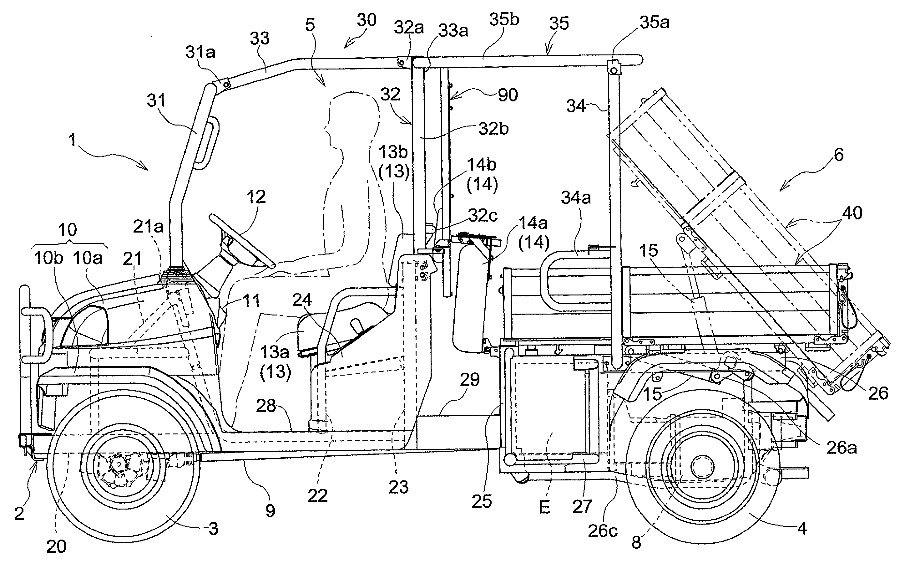
[0007]An object of the present invention is to provide a pickup-style work vehicle that has a loading floor that can be moved to a dumping position without having to move the backseat from its use position, thus improving efficiency of a dumping operation.
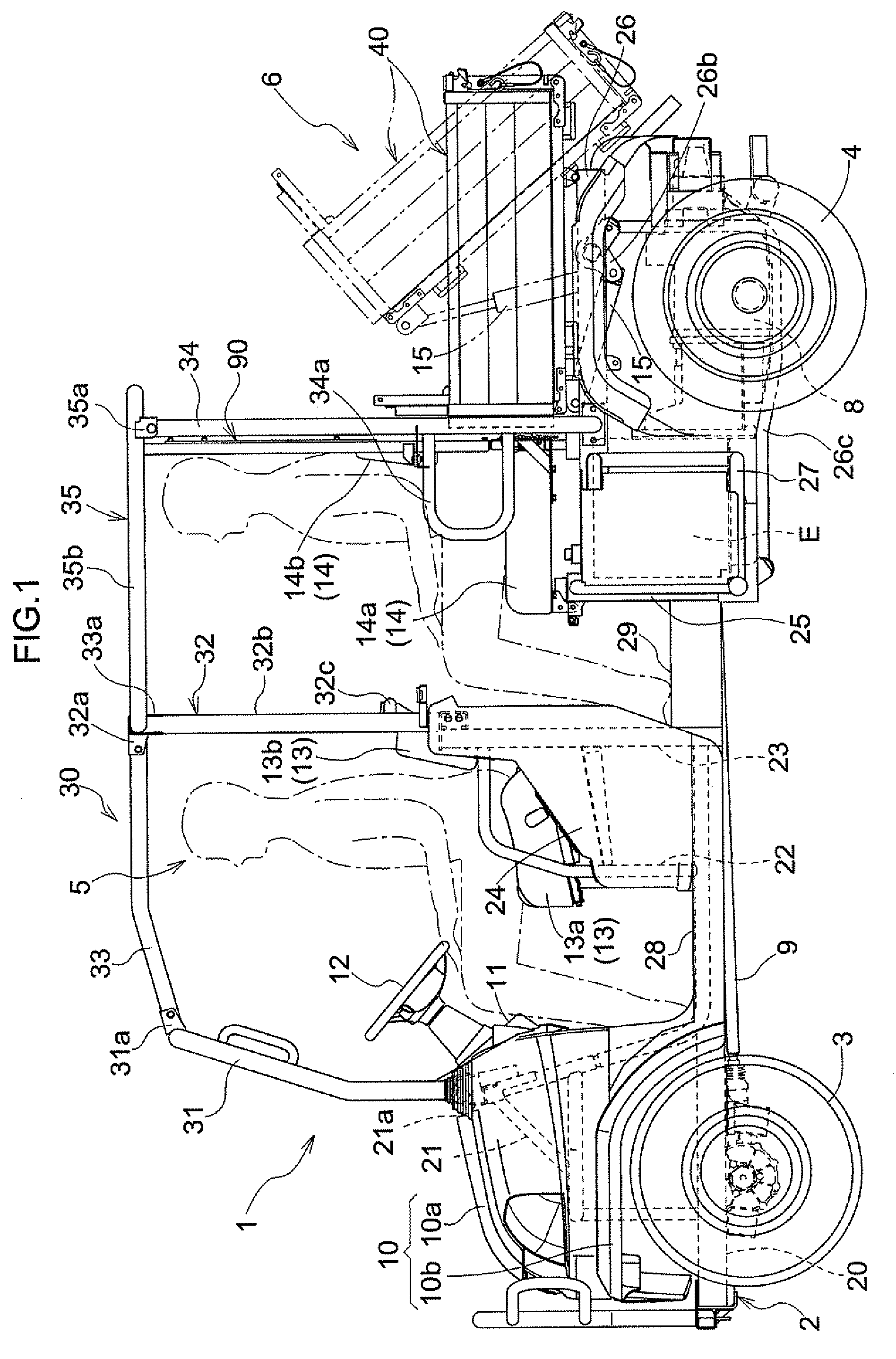
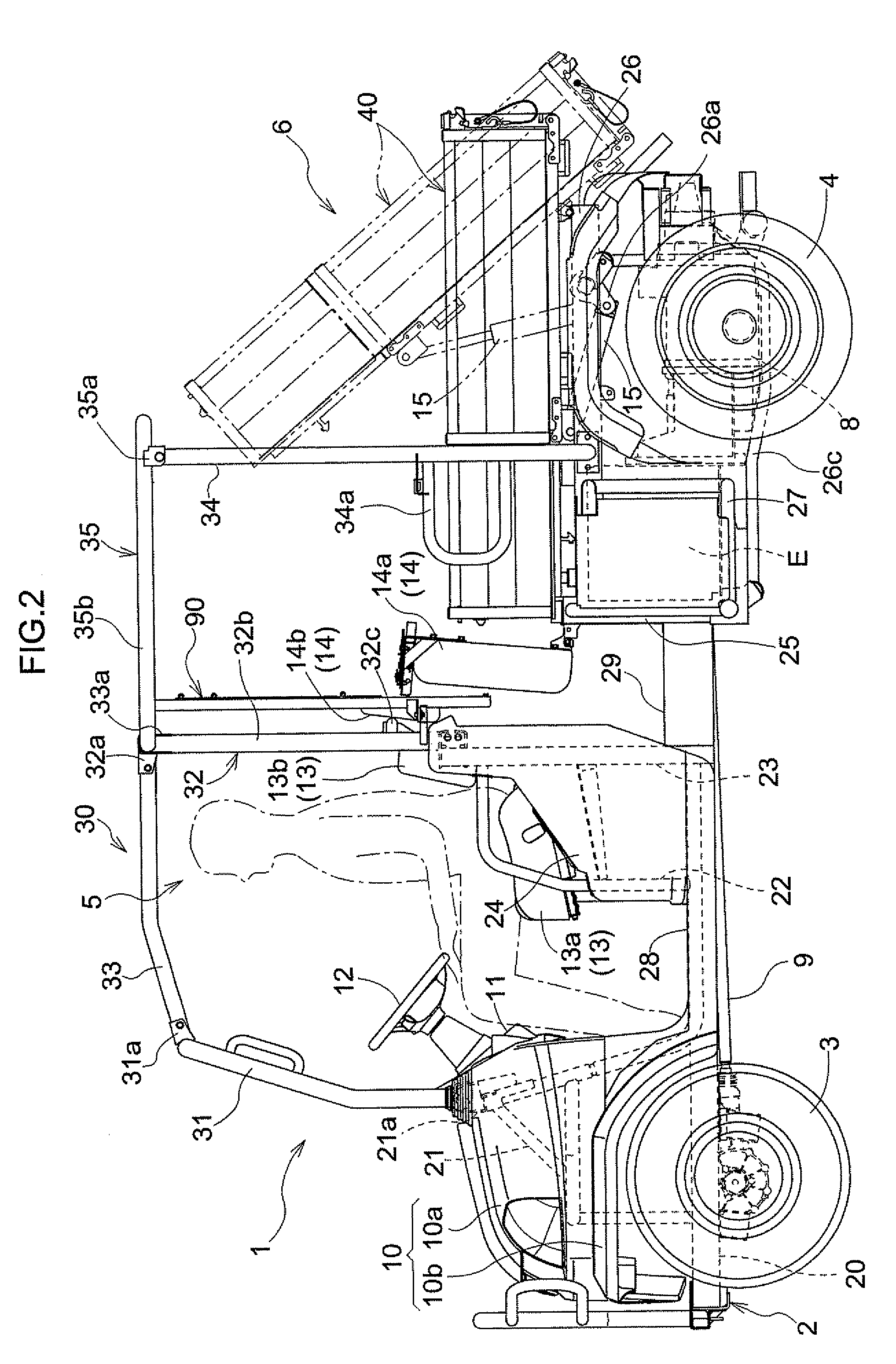
[0009]With this configuration, the front wall portion and the front bottom portion of the loading floor are moved rearwardly when the loading floor is changed from the first state to the second state. With the loading floor in the second state, the posture of the backseat is changed to the second posture and the backseat in its use state then can be positioned in a space created by rearwardly moving the front wall portion and the front bottom portion of the loading floor. Since the front bottom portion of the loading floor is moved rearwardly when the loading floor is moved to the second state, the front bottom portion will not be located underneath the backseat in the second posture. Therefore, even when the front bottom portion is lifted during a dumping operation of the loading floor in the second state, the raising front bottom portion will not interfere with the backseat in the second posture, thus allowing for a dumping operation of the loading floor without having to move the backseat out of the use state which is the second state.
[0010]In the present pickup-style work vehicle, the loading floor can be moved to a dumping position without having to check the state of the backseat or to change the backseat from the second posture to the first posture. This makes a dumping operation simpler and quicker, thus improving efficiency of the dumping operation of the loading floor. In addition, since the loading floor during a dumping operation will not interfere with the backseat in the second posture, any damage to the backseat can be prevented.

Problems solved by technology

Therefore, since the loading floor interferes with the backseat, it was not possible for the loading floor to be moved to its dumping position when the backseat is in the use state in which the backseat is pivoted rearwardly (a configuration in which passengers can sit on the backseat).
Therefore, there exists a problem where it is difficult to perform the dumping operation of the loading floor simply and quickly, reducing efficiency of the dumping operation of the loading floor.
Further, there exits an additional problem that the backseat may be damaged if the loading floor is moved to its dumping position accidentally when the backseat is in the use state.

Method used


Image

  • Pickup-style work vehicle
  • Pickup-style work vehicle
  • Pickup-style work vehicle

Examples


second embodiment

[0144]In the first embodiment described above, the loading floor size changeover mechanism was shown and described in which the right and left forward side wall portions 45 were folded rearwardly after raising and folding the front bottom portion 42 with the front wall portion 46 rearwardly to the upright position. Different order for folding the front wall portion 46, the front bottom portion 42, and the right and left forward side wall portions 45 can be adapted. For example, the loading-platform size changeover mechanism may be configured such that the front bottom portion 42 with the front wall portion 46 are raised rearwardly to the upright position folded after folding the right and left forward side wall portions 45 rearwardly.

[0145]While in the first embodiment described above, the loading-platform size changeover mechanism was shown and described in which the loading floor 40 was switched between the extended state and the shortened state by folding the front wall portion 4...

third embodiment

[0149]A backseat posture change mechanism having a different structure may be adopted in lieu of the backseat posture change mechanism, in the first and second embodiments described above, which change the posture of the backseat 14 to the first and second postures. More specifically, for example, the rear seat bottom 14a in the prone posture is fixed to backseat support frame 25, etc., and the seat back 14b is fixed to the partition member 90. And the backseat posture change mechanism may be configured to change the posture of the backseat 14 to the first posture in which the seat back 14b is moved forward, and to the second posture in which the seat back 14b is moved rearward. In this case, the height of the lower end of the front bottom portion 42 in the extended state is set to be higher than the height of an upper end of the rear seat bottom 14a so that a predetermined gap is formed in the vertical direction between the rear seat bottom 14a and the front bottom portion 42 in th...


PUM


Abstract

A pickup-style work vehicle comprises a front driver's seat, a backseat, a loading floor that is located rearwardly of the backseat and that can be moved to a dumping position, a loading floor size changeover mechanism, and a backseat posture change mechanism. The loading floor size changeover mechanism changes the size of the loading floor between a first state in which a front wall portion and a front bottom portion of the loading floor are moved forwardly in a fore-and-aft direction and a second state in which the front wall portion and the front bottom portion of the loading floor are moved rearwardly in a fore-and-aft direction. The backseat posture change mechanism changes a posture of the backseat between a first posture which is a non-use state and a second posture which is a use state. The fore-and-aft dimension of the backseat in the first posture is less than a fore-and-aft dimension of the backseat in the second posture. the backseat in the first posture is located immediately forwardly of the loading floor in the first state and the backseat in the second posture is located immediately forwardly of the loading floor in the second state.

Description

BACKGROUND OF THE INVENTION[0001]1. Field of the Invention[0002]The present invention relates to a pickup-style work vehicle having a front driver's seat, a backseat, and a loading floor that is arranged rearwardly of the backseat and that can be moved to a dumping position.[0003]2. Description of the Related Art[0004]A conventional pickup-style work vehicle is known from U.S. Pat. No. 6,994,388 (see FIG. 2, FIGS. 4-7), which has a front driver's seat (shown at 3 in FIG. 2), a backseat (shown at 4 in FIG. 2) and a loading floor (shown at 2 in FIG. 2) that is arranged rearwardly of the backseat and that can be moved a dumping position. In this work vehicle, a space for the backseat, when pivoted rearwardly, is created by moving the attachment position of a divider (shown at 5 in FIG. 2 of the patent) rearwardly, and by moving the front side wall rearwardly (shown at 21 of FIGS. 6 and 7). This allows the backseat to be pivoted rearwardly to its use state (a configuration in which pass...

Claims


Application Information

Patent Timeline
Patent Type & Authority Patents(United States)
IPC IPC(8): B62D25/00
CPCB60N2/305B60P1/16B60P1/26B62D47/003B60P3/423B62D33/0273B62D33/037B60P1/283
Inventor SHIMAMURA, TERUONAKAMURA, NORIMIHIROOKA, YOSHIMINAKAMURA, TARO
Owner KUBOTA LTD
Why Eureka
Try Eureka