
Electric power converting device and power converting method for controlling doubly-fed induction generator

a technology of induction generator and conversion device, which is applied in the direction of electric generator control, dynamo-electric converter control, machines/engines, etc., can solve the problems of generators that cannot be controlled directly, generators cannot recover (generate) energy from the system, and it is difficult to properly control the active power and the power factor of the stator sid

Active Publication Date: 2009-08-25
KOREA ELECTROTECH RES INST
View PDF9 Cites 50 Cited by
  • Summary
  • Abstract
  • Description
  • Claims
  • Application Information

AI Technical Summary

Benefits of technology

The present invention provides an electric power converting device for controlling a doubly-fed induction generator that can separately generate auxiliary electric power and control the DC link voltage and power factor to be maintained at 1, even in an unbalanced load condition. The device includes a synchronous generator, an auxiliary converter, a DC link capacitor, and a grid-side converter. The generator-side converter converts the AC power into a DC power, which is then converted into a balanced voltage and maintained at 1 by the DC link capacitor. The grid-side converter re-converts the DC power back into an AC power for application to the AC system. The device automatically synchronizes the stator voltage of the generator with the system voltage and controls the active power and reactive power as it is affected by the installation position of the encoder. The method of controlling the device includes the steps of turning off the switches, measuring the speed of the new and renewable energy source, comparing it with a reference speed, and interconnecting the auxiliary converter and the DC link capacitor if the terminal voltage of the battery exceeds a reference voltage. The technical effects of the invention include improved control of the generator's voltage and power factor, as well as improved stability and reliability of the power converting device.

Problems solved by technology

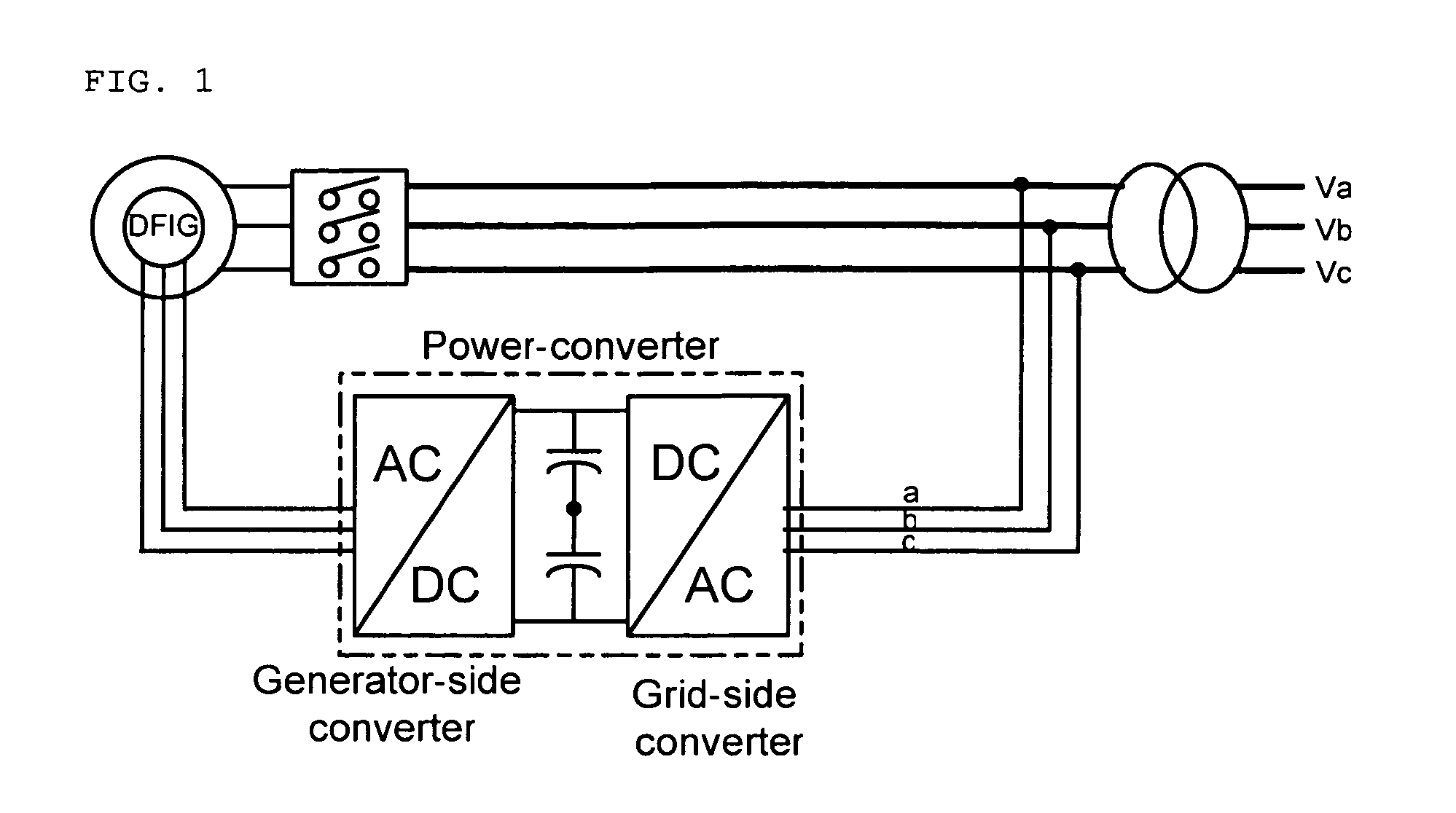
However, such a configuration entails a problem in that it can recover energy from the system but cannot recover (generate) energy from the system using the grid-side converter.
In addition, this configuration encounters a structural problem in that an active power and a power factor of a stator side of the doubly-fed induction generator cannot be controlled directly.
Specifically, the power factor is controlled by a passive capacitor, and energy transferred to the system employs a heat consumption method using a damping resistance, which makes it difficult to properly control the active power and the power factor of the stator side.
Also, 20% or so of the amount of electricity generation is recovered from the rotor winding and this recovered energy is consumed as heat, which leading to a degradation of efficiency.
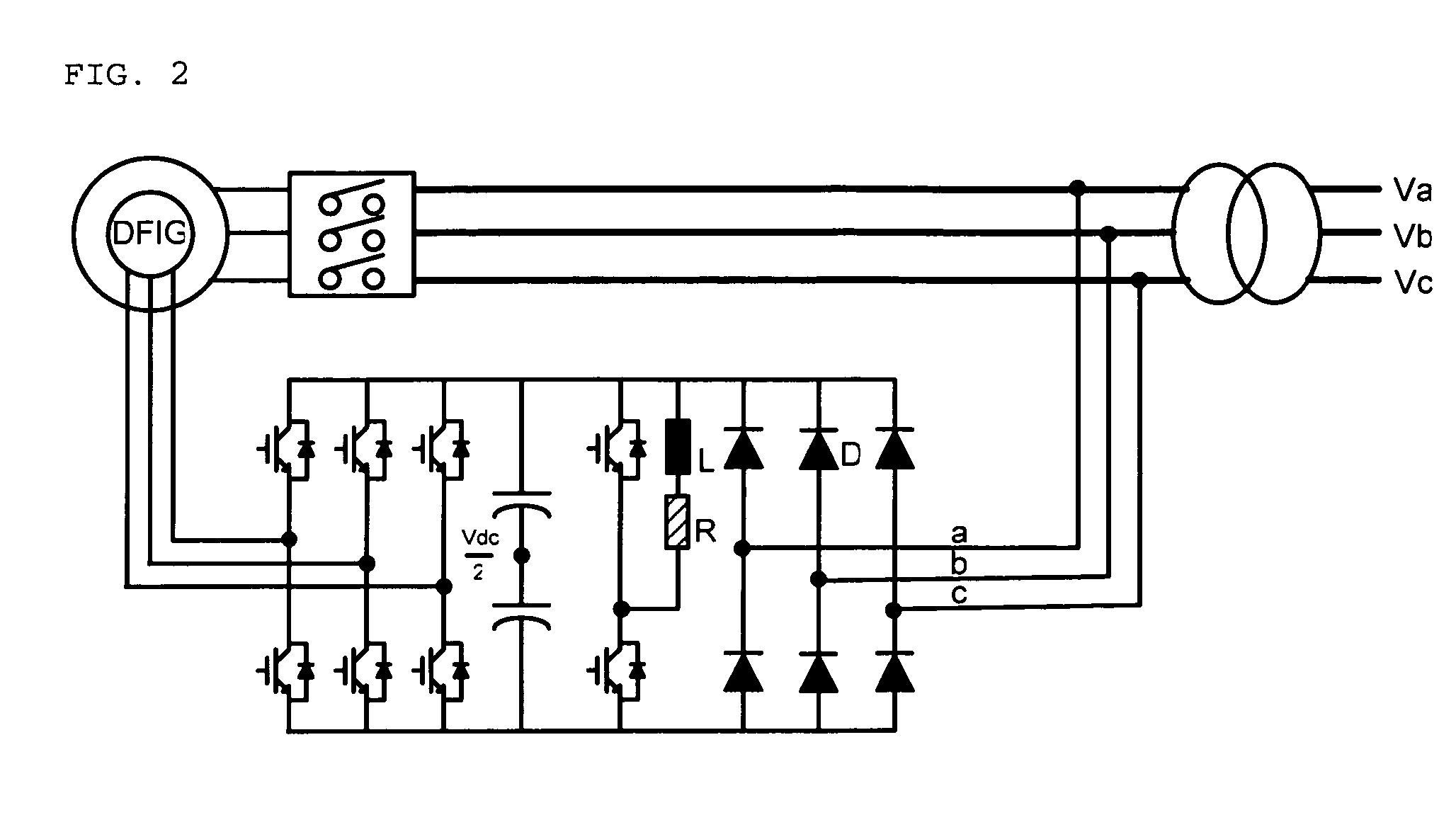
However, the above structure also has a problem in that in case where the system is unstable and instantaneous power interruption occurs except an ordinary state, the generated voltage is not in a three-phase balanced state.
But, there is caused a problem in that since the above-mentioned control properties cannot be maintained in an unbalanced condition (load, power supply, etc.), the new & renewable energy power generation system (wind power / tidal current / tidal current power / wave power generation system) is stopped.
Furthermore, the above structure entails a problem in that it can be used only in an environment where the system voltage exists since the power system voltage is directly applied to the stator winding to provide a magnetic flux component and hence the above structure is usable in a system-connected condition.

Method used


Image

  • Electric power converting device and power converting method for controlling doubly-fed induction generator
  • Electric power converting device and power converting method for controlling doubly-fed induction generator
  • Electric power converting device and power converting method for controlling doubly-fed induction generator

Examples


Embodiment Construction

[0069]Reference will now be made in detail to the construction and operation of an electric power converting device for controlling doubly-fed induction generators of the present invention with reference to the attached drawings. For the sake of facilitating a person's comprehensive understanding, it is noted that the same reference numerals will be used to denote identical or similar elements throughout the drawings.

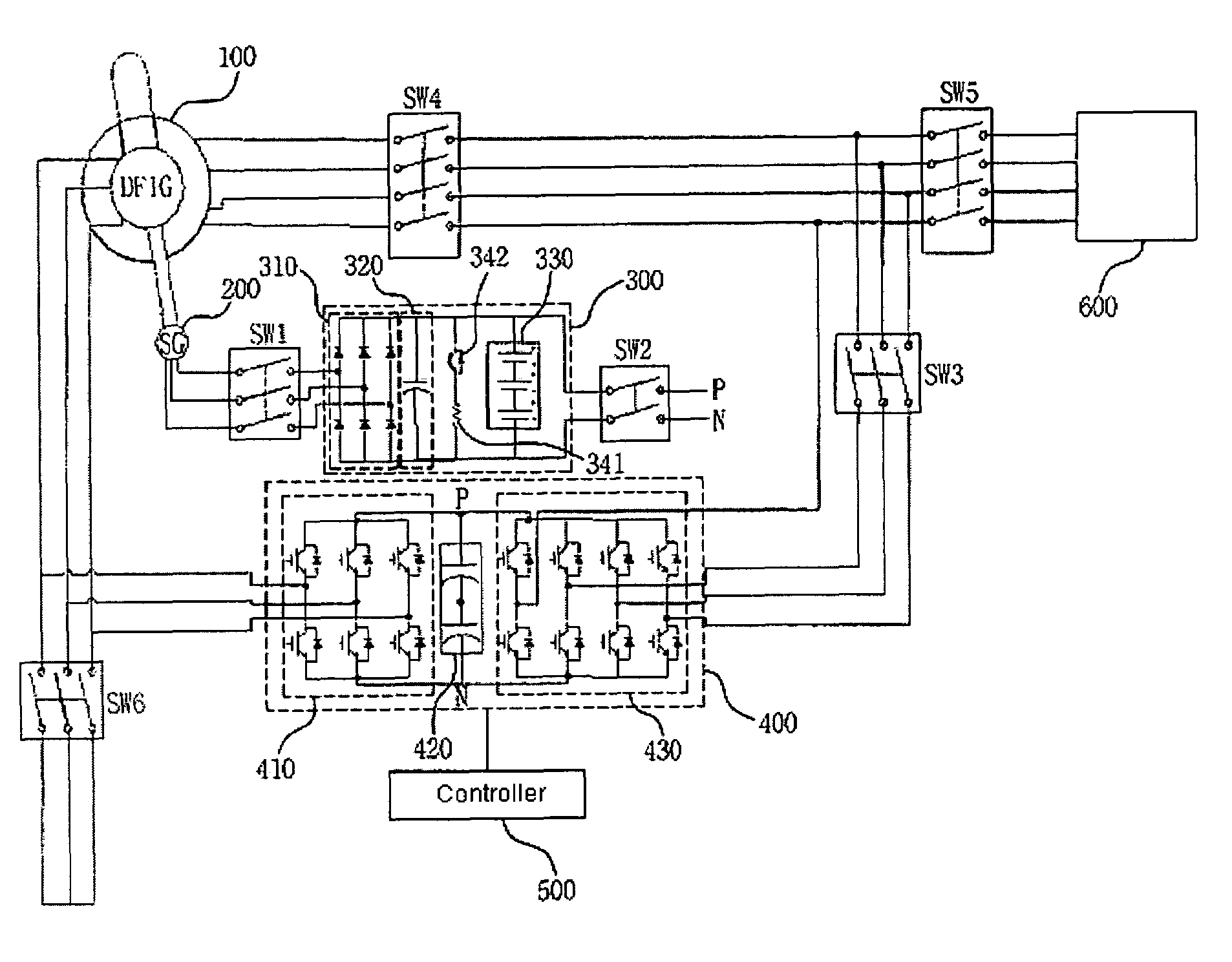
[0070]FIG. 4a is a block diagram illustrating the construction of an electric power converting device for controlling a doubly-fed induction generator according to the present invention, FIG. 4b is a circuit diagram illustrating the construction of an electric power converting device for controlling a doubly-fed induction generator according to one embodiment of the present invention, FIG. 5 is a schematic view illustrating the construction of a to-be-controlled doubly-fed induction generator of an electric power converting device for controlling a doubly-fed induction ...


PUM


Abstract

Disclosed herein is an electric power converting device and power converting method for controlling doubly-fed induction generators, which provides a synchronous generator for generating auxiliary electric power independently of a doubly-fed induction generator so as to generate electricity even in a system power-free environment, a grid-side converter is composed of a three-phase four-wire converter so as to generate a balanced voltage even in an unbalanced load condition and automatically synchronize a stator voltage of a doubly-fed induction generator and a system voltage with each other.

Description

CROSS-REFERENCE TO RELATED APPLICATIONS[0001]This application claims the benefit under 35 U.S.C. §119(a) of Korean Patent Application No. 10-2005-0135062, filed in the Korean Intellectual Property Office on Dec. 30, 2005, the entire disclosure of which is incorporated herein by reference.BACKGROUND OF THE INVENTION[0002]1. Field of the Invention[0003]The present invention relates to an electric power converting device, and more particularly, to an electric power converting device and power converting method for controlling doubly-fed induction generators, which provides a synchronous generator for generating auxiliary electric power independently of a doubly-fed induction generator so as to generate electricity even in a system power-free environment, a grid-side converter is composed of a three-phase four-wire converter so as to generate a balanced voltage even in an unbalanced load condition and automatically synchronize a stator voltage of a doubly-fed induction generator and a s...

Claims


Application Information

Patent Timeline
Patent Type & Authority Patents(United States)
IPC IPC(8): H02P9/48
CPCH02J3/386H02P9/46H02P9/007Y02E10/763H02J2300/28H02J3/381Y02E10/76H02J3/44H02M3/38
Inventor PARK, JUNG-WOOLEE, KI-WOOKKIM, DONG-WOOK
Owner KOREA ELECTROTECH RES INST
Learn More