Fixing device for image forming apparatus and control method thereof

a technology of fixing device and image forming apparatus, which is applied in the direction of electrographic process apparatus, instruments, optics, etc., can solve the problems of inability to acquire predetermined image quality, excessive melting of toner layer surface, and inability to fix image quality, etc., to prevent color difference, stable fix image, and uniform melting

Inactive Publication Date: 2009-08-25
KK TOSHIBA +1
View PDF8 Cites 6 Cited by
  • Summary
  • Abstract
  • Description
  • Claims
  • Application Information

AI Technical Summary

Benefits of technology

[0010]Thus, according to an aspect of the invention, as the toner layer of a color toner image with the thick toner layer is heated from above and below, the toner layer is evenly melted and a color difference is prevented, thus providing a stable fixed image. Moreover, a fixing device for an image forming apparatus and a control method thereof are provided which enable reduction of power consumption while fixation is not carried out, and hence energy saving, without losing the convenience for the user waiting long for a fixing operation.

Problems solved by technology

Therefore, when the temperature of the heat roller is raised to melt the thick toner layer, only the surface of the toner layer melts excessively.
Moreover, for a color image, a difference in the way of melting of the toner layer causes a color difference in the image and predetermined image quality cannot be acquired.
However, also in such a conventional fixing device, heating control of the heat roller and the press roller is only on-off control of the heating source by application of predetermined power for each operation mode.
Therefore, the heat roller and the press roller tend to have a temperature ripple and this temperature ripple may cause a color difference in the fixed image.
In the image forming apparatus, the power consumption by the fixing device is large and the energy saving in the fixing device largely affects the energy saving in the entire apparatus.
However, power is also consumed in the standby state as well as while copying is being carried out.
Moreover, in the conventional color fixing device, in which both the heat roller and the press roller are heated, the power consumption in the standby state may increase.

Method used


Image

  • Fixing device for image forming apparatus and control method thereof
  • Fixing device for image forming apparatus and control method thereof
  • Fixing device for image forming apparatus and control method thereof

Examples


Embodiment Construction

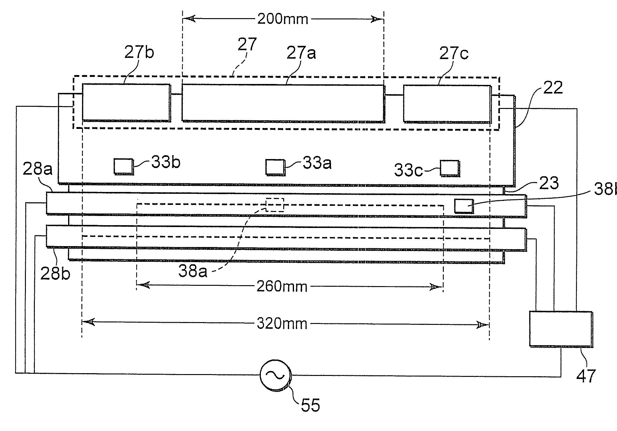
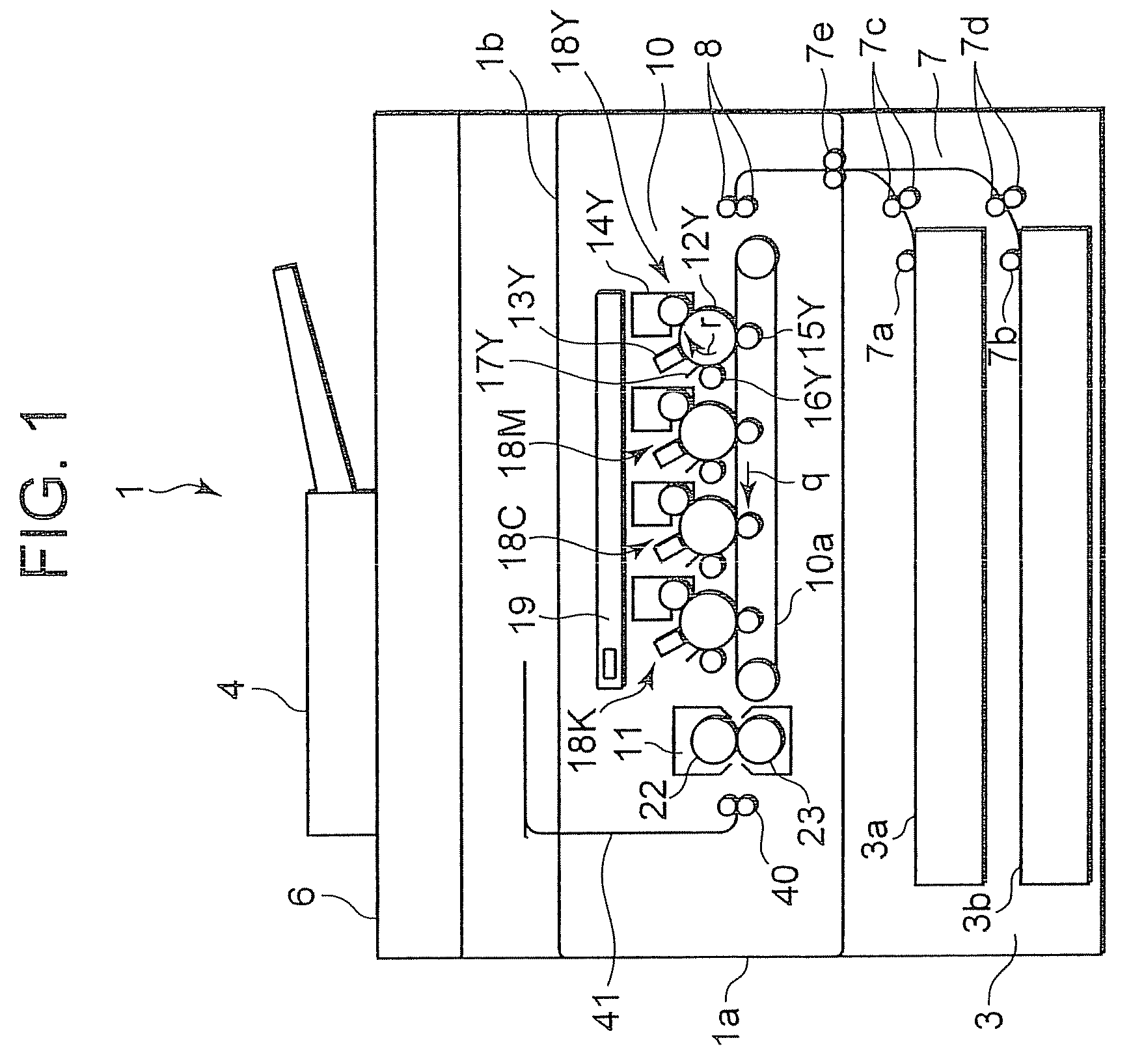
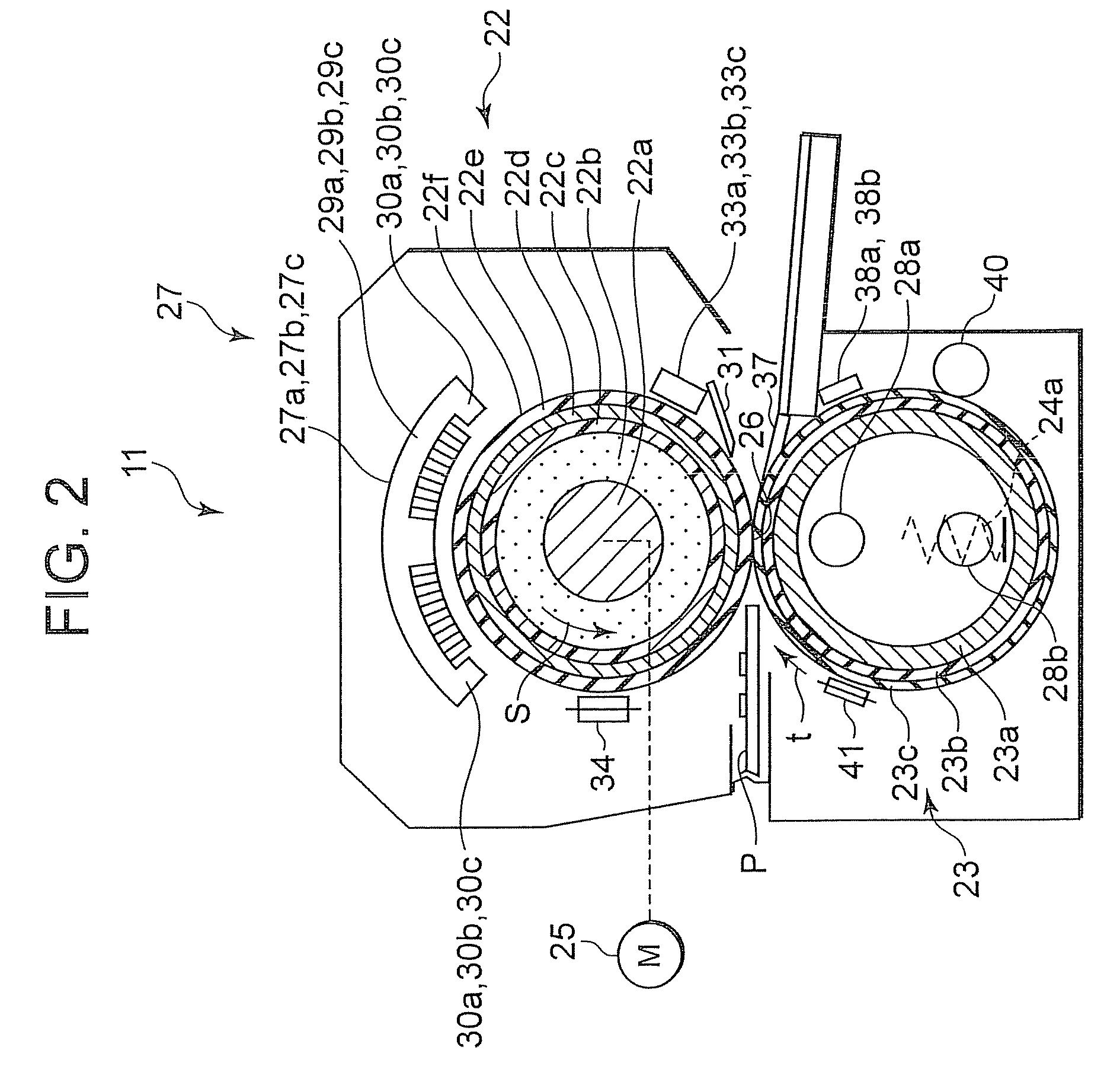
[0016]Hereinafter, an embodiment of the invention will be described in detail with reference to the accompanying drawings. FIG. 1 is a schematic configuration view showing a color image forming apparatus 1 according to an embodiment of the invention. A scanner unit 6 that reads an original supplied by an automatic document feeder 4 is provided at the top of the color image forming apparatus 1. The color image forming apparatus 1 has a cassette mechanism 3 that supplies a sheet paper P, which is a fixing target medium, to an image forming unit 10.

[0017]The cassette mechanism 3 has first and second paper feed cassettes 3a and 3b. In a carrier path 7 from the paper feed cassettes 3a, 3b to the image forming unit 10, pickup rollers 7a, 7b that take out a sheet paper from the paper feed cassettes 3a, 3b, separation carrier rollers 7c, 7d, carrier rollers 7e, and resist rollers 8 are provided. A fixing device 11 that fixes a toner image that is formed on the sheet paper P by the image for...


PUM


Abstract

A fixing device of this invention enables variable control of power to be supplied to a heat roller side or a press roller side in accordance with the temperature of the heat roller and the press roller while each mode is carried out. The heating range of a first induction heating coil on the heat roller side and the heating range of a first halogen lamp heater on the press roller side are set differently. In a copy mode, the temperature of the heat roller and the press roller is controlled in detail, and also controlled in accordance with the size of a sheet paper. In a copy standby mode, only the power required for maintaining a set temperature is supplied.

Description

BACKGROUND OF THE INVENTION[0001]1. Field of the Invention[0002]The present invention relates to a fixing device in an image forming apparatus for fixing onto a sheet paper, by heating and pressurizing, a toner image formed in the image forming apparatus using an electrophotographic process such as a copy machine, printer or facsimile, and a control method thereof.[0003]2. Description of the Background[0004]As a fixing device incorporated in an image forming apparatus using an electrophotographic process such as a copy machine, printer or facsimile, there is a fixing device that fixes a toner image on a sheet paper by heating and pressurizing. In such a fixing device, a sheet paper is inserted between a pair of rollers including a heat roller and a press roller, or in a nipping part formed between similar belts, and a toner image is fixed thereon by being heated and pressurized. Meanwhile, a full-color toner image formed by superimposed toner images of plural colors has a toner laye...

Claims


Application Information

Patent Timeline
Patent Type & Authority Patents(United States)
IPC IPC(8): G03G15/20
CPCG03G15/2007G03G15/2039G03G15/5004G03G2215/00734
Inventor TAKAGI, OSAMUKINOUCHI, SATOSHITSUEDA, YOSHINORISONE, TOSHIHIRO
Owner KK TOSHIBA
Why Eureka
Try Eureka