Phase-change cold-storage device for air conditioner

A phase change cold storage and cold storage technology, which is applied in air conditioning systems, household refrigeration devices, applications, etc., can solve the problems of low utilization rate of cold storage, large heat transfer resistance, large flow resistance, etc., to improve cold storage capacity and cold storage efficiency. , The effect of improving economy and small flow resistance

Inactive Publication Date: 2006-02-08
NANJING UNIV
View PDF0 Cites 12 Cited by
  • Summary
  • Abstract
  • Description
  • Claims
  • Application Information

AI Technical Summary

Problems solved by technology

[0005] (2) Urban power consumption is growing rapidly, but the urban power grid cannot adapt to it, resulting in a situation where there is no power to be sent or distributed
Most inorganic phase change cold storage materials are corrosive and have the disadvantages of supercooling and phase separation during the phase change process, which affects their cold storage capacity; while organic phase change cold storage materials are not only less corrosive, but also have a large latent heat of phase change. There is almost no disadvantage of phase separation during the phase change process, and the chemical performance is stable and the price is cheap
However, organic phase change cold storage materials generally have the disadvantage of low thermal conductivity, which leads to poor heat transfer performance and low utilization rate of cold storage in the application of cold storage systems.
The heat exchange tubes of existing regenerators all adopt serpentine coil or "U"-shaped tube structure. The disadvantages of this structure are: large heat transfer resistance, large flow resistance, and phase change cold storage materials cannot be uniformly distributed in the regenerator. Solidification and melting affect the cold storage capacity and cold storage efficiency of the cold storage air conditioning system

Method used


Image

  • Phase-change cold-storage device for air conditioner
  • Phase-change cold-storage device for air conditioner
  • Phase-change cold-storage device for air conditioner

Examples


Embodiment Construction

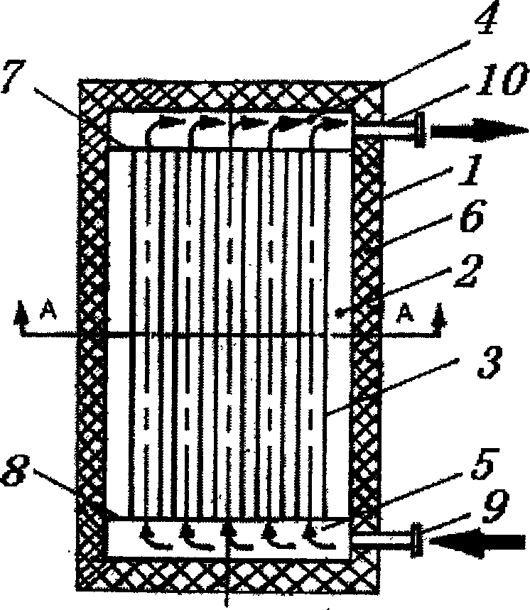
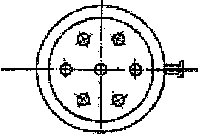
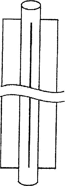
[0026] A phase-change cool accumulator for air-conditioning according to the present invention comprises a barrel body 1 of the cool accumulator, a phase-change cold storage material 2 , a heat exchange tube 3 , an upper liquid collection chamber 4 and a lower liquid collection chamber 5 . A group of 7 heat exchange tubes 3 loaded with refrigerant are set in the regenerator barrel 1 made of thermal insulation material 6; the heat exchange tubes 3 are copper tubes or steel tubes, and rectangular finned tubes with good thermal conductivity can be used Or circular finned tubes, rectangular fins or circular fins are made of copper or aluminum, with a thickness of 2 mm. The barrel body 1 of the cold accumulator adopts a cylindrical steel insulation structure. The upper liquid collection chamber 4 is located at the upper end of the heat exchange tube 3, and the lower liquid collection chamber 5 is located at the lower end of the heat exchange pipe 3; an upper end for forming the upp...


PUM


Abstract

The phase change cold accumulator includes cold accumulator barrel with one set of heat exchange pipe with coolant, phase change cold accumulating material, upper liquid collecting chamber located in and communicated to the upper end of the heat exchange pipe, and lower liquid collecting chamber located in and communicated to the lower end of the heat exchange pipe. The cold accumulator barrel is provided with coolant inlet communicated with the lower liquid collecting chamber and coolant outlet communicated with the upper liquid collecting chamber, and the phase change cold accumulating material is sealed inside the cavity comprising the cold accumulator barrel, the heat exchange pipe, the upper end plate and the lower end plate. The present invention has small heat transfer resistance, small flow resistance, high cold accumulating and releasing efficiency, and homogeneous solidification and melting of the phase change cold accumulating material, and is suitable for various cooling air conditioners.

Description

1. Technical field [0001] The invention relates to a refrigerating air conditioner, in particular to a phase change cold accumulator for an air conditioner. 2. Background technology [0002] Since the reform and opening up, my country's comprehensive national strength and people's living standards have been greatly improved. As one of the basic industries of the national economy, the electric power industry has achieved considerable development. However, the growth of electric power still cannot meet the needs of the rapid development of the national economy and the sharp increase of people's daily electricity consumption, and the situation of power shortage in the whole country still exists. In the summer peak of 2005, the overall national power gap was about 30 million kilowatts. [0003] At present, the tight power supply is mainly manifested in the following aspects: [0004] (1) The load rate of the power grid is low, the peak-to-valley difference of the system incre...

Claims


Application Information

Patent Timeline
Patent Type & Authority Applications(China)
IPC IPC(8): F24F5/00F25D3/00
CPCY02E60/147Y02E60/14
Inventor 方贵银杨帆邢琳李辉
Owner NANJING UNIV
Why Eureka
Try Eureka