
Rotational airfoil balance system

a technology of airfoil and blade balance, which is applied in the direction of rotors, vessel construction, marine propulsion, etc., can solve the problems of relatively high manufacturing cost of blade balance systems of this type, and conventional blade balance systems require a relatively significant quantity of weight to be added, so as to reduce the quantity of weight

Inactive Publication Date: 2009-09-01
HAMILTON SUNDSTRAND CORP
View PDF14 Cites 6 Cited by
  • Summary
  • Abstract
  • Description
  • Claims
  • Application Information

AI Technical Summary

Benefits of technology

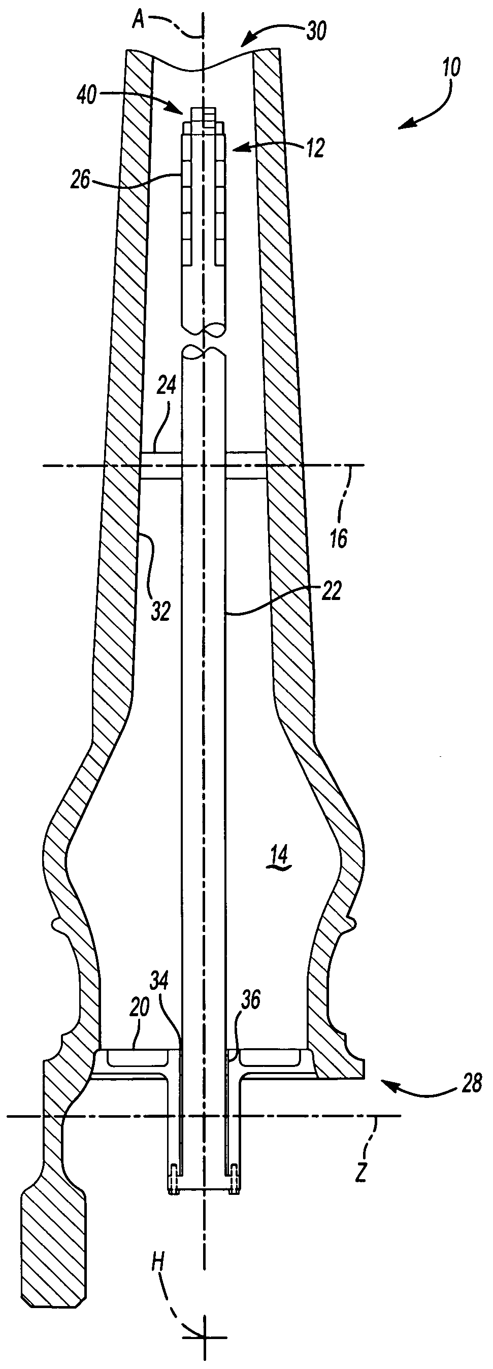
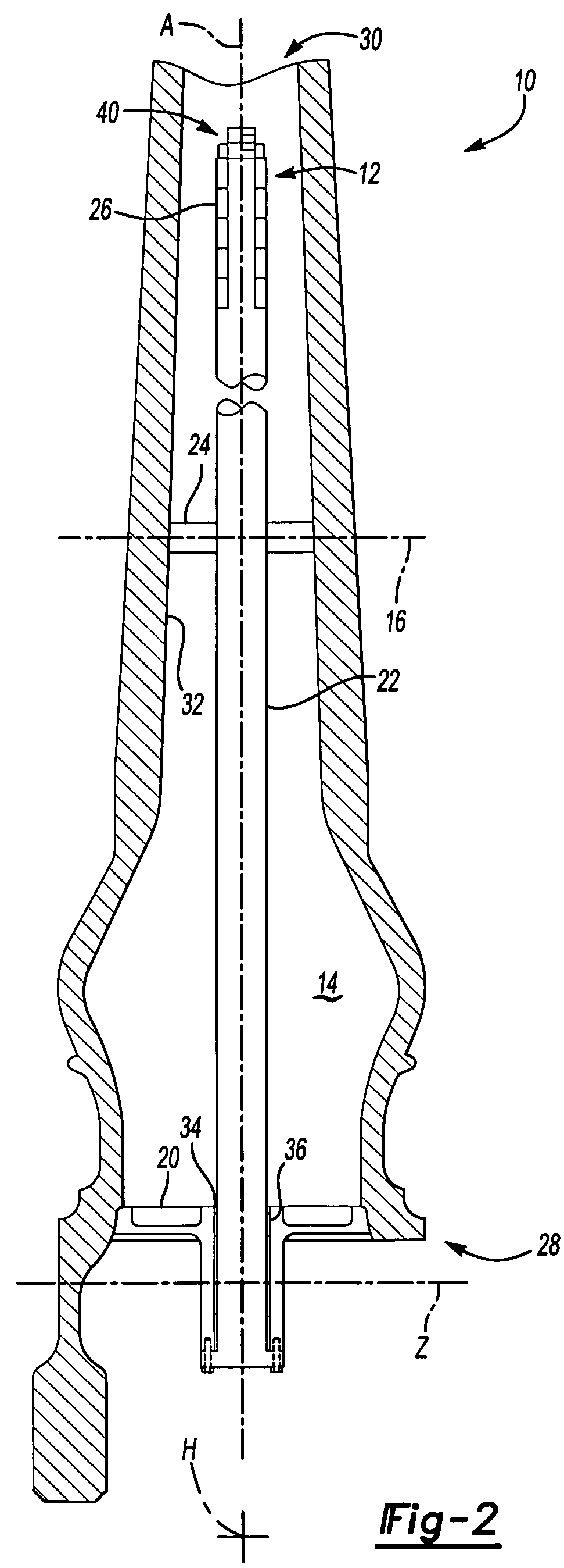
The present invention is a balance system for a rotational airfoil that effectively balances the airfoil with a minimal addition to the overall blade weight. The system includes a bulkhead, an elongated member, a support, and at least one balance weight. The elongated member extends through the bulkhead along the longitudinal axis towards the tip segment of the airfoil assembly. The tip segment of the elongated member extends along the longitudinal axis proximate to the mid-span segment of the airfoil assembly. The at least one balance weight is mounted to the tip segment to balance the airfoil assembly. The balance weights are located on the elongated member outside of the mid-span segment along the longitudinal axis, which reduces the amount of weight needed to balance the airfoil. This design helps to minimize the impact on the overall blade weight.

Problems solved by technology

Disadvantageously, blade balance systems of this type are relatively expensive to manufacture due the relatively large amount of machining required to provide the cavity within the blade bore.
Although effective, conventional blade balance systems require a relatively significant quantity of weight to be added relative to the overall weight of a blade.

Method used


Image

  • Rotational airfoil balance system
  • Rotational airfoil balance system
  • Rotational airfoil balance system

Examples


Embodiment Construction

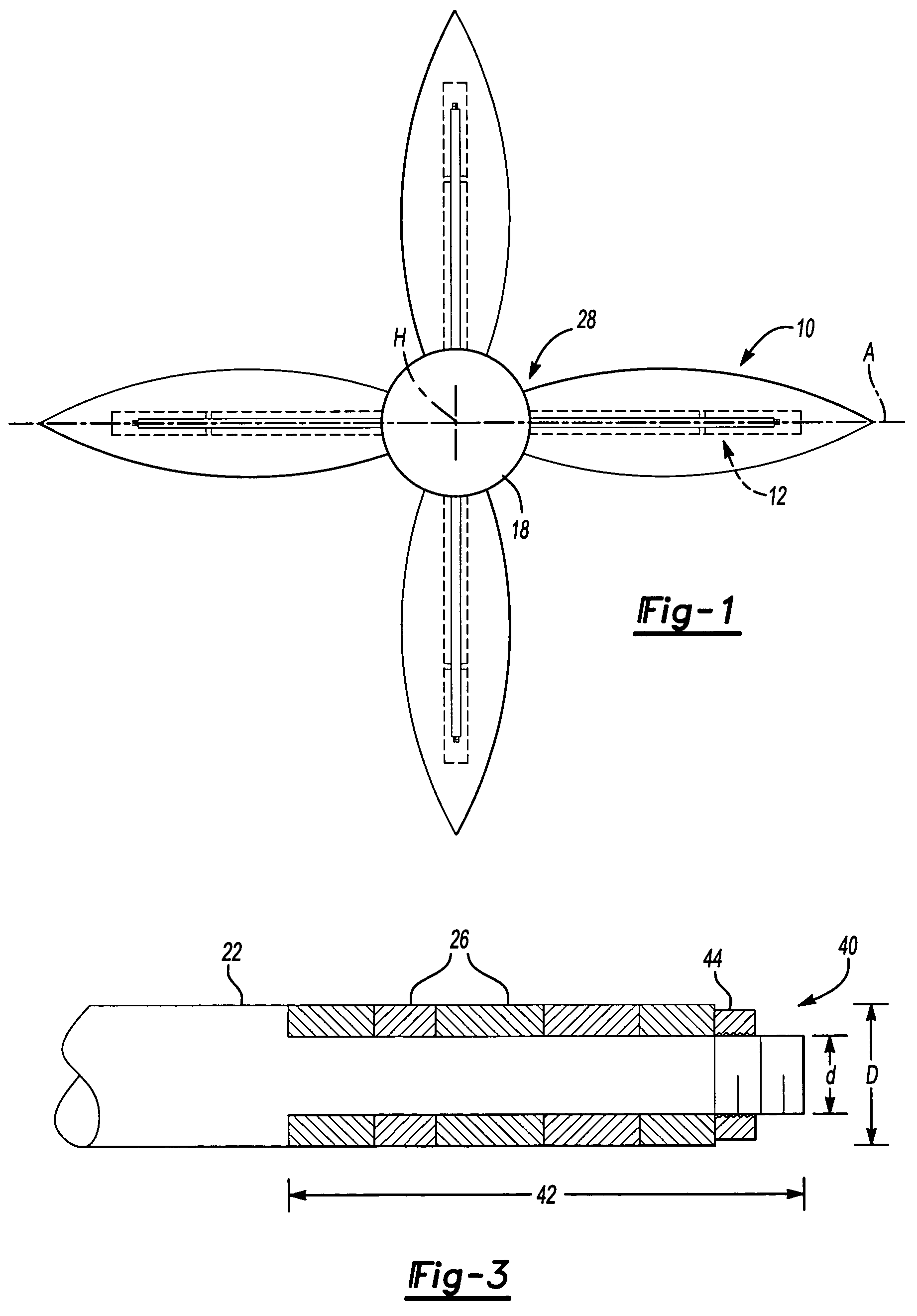
[0016]Referring to FIG. 1, a multitude of rotational airfoil assemblies 10 are mounted to a hub assembly 18 at an airfoil root segment 28 for rotation about a hub axis H. Each rotational airfoil assembly 10 includes a balance system 12 according to the present invention. The rotational airfoil assembly 10 is shown and described herein in terms of a propeller blade, however, it should be understood that various other airfoil assemblies such as rotor blade systems may employ the configuration disclosed herein.

[0017]Referring to FIG. 2, the rotational airfoil assembly 10 includes a bore 14 which defines a longitudinal axis A. The rotational airfoil assembly 10 generally defines a longitudinal span between the airfoil root segment 28 and an airfoil tip segment 30. An airfoil mid-span segment 16 is defined generally between the airfoil root segment 28 and the airfoil tip segment 30 of the rotational airfoil assembly 10.

[0018]The balance system 12 permits dynamic balance of the rotational...


PUM


Abstract

A balance system for a rotational airfoil assembly includes a bulkhead, an elongated member, a support member and at least one balance weight. The elongated member extends through the bulkhead along a bore toward an airfoil tip segment of the airfoil assembly. The balance weights are mounted to a tip segment of the elongated member positioned within the bore outboard of an airfoil mid-span segment of the airfoil assembly. A reduced quantity of weight is required to balance the airfoil assembly because of the location of the balance weights outside of the mid-span segment of the airfoil assembly.

Description

BACKGROUND OF THE INVENTION[0001]The present invention relates to a rotational airfoil assembly, and more particularly to a balance system therefor.[0002]Aircraft such as turboprops, tilt rotors and helicopters include rotational airfoil assemblies such as propeller blade and rotor blade systems. Propeller blades are secured to a hub of an aircraft via a retention assembly. The blades are dynamically balanced about the axis of rotation of the hub to minimize vibration and noise that may occur during operation. Specifically, the blades must be balanced about the axis of rotation of the hub to balance both the action of a centrifugal force produced by the rotation of the blades and the moments caused by aerodynamic forces generated by the relative speed of the blades with respect to the air.[0003]One conventional method of blade balancing includes machining a cavity into a blade on an inboard side of the blade and inserting lead wool into the machined cavity until the proper balance i...

Claims


Application Information

Patent Timeline
Patent Type & Authority Patents(United States)
IPC IPC(8): B64C11/20
CPCF01D7/00F04D29/324F04D29/662F04D29/34Y02T50/673Y02T50/672B64C11/008B64C27/008Y02T50/60
Inventor CARVALHO, PAUL ARMAND
Owner HAMILTON SUNDSTRAND CORP
Learn More