Imaging device having chromatic aberration suppression

a chromatic aberration and image technology, applied in the direction of solid-state device signal generators, color signal processing circuits, picture signal generators, etc., can solve the problems of memory capacity, image similarly becomes inferior in sharpness, generating false colors, etc., to achieve accurate suppression of chromatic aberration, improve image quality, and simplify configuration

Inactive Publication Date: 2009-09-01
MONUMENT PEAK VENTURES LLC
View PDF6 Cites 33 Cited by
  • Summary
  • Abstract
  • Description
  • Claims
  • Application Information

AI Technical Summary

Benefits of technology

[0008]Accordingly, the present invention provides a device capable of accurately suppressing chromatic aberration with a simpler configuration and enhancing image quality.
[0019]According to the present invention, data for correction purpose do not need to be stored in memory in advance. Chromatic aberration can be suppressed simply and accurately. Since chromatic aberration of the image signal having undergone gamma correction is suppressed, variations in brightness level attributable to gamma correction can also be suppressed. Further, even when chromatic aberration in the image signal that is to undergo gamma correction, a brightness component and chromatic aberration can be simultaneously corrected. Accordingly, even in subsequent gamma correction, a brightness level can be maintained at an appropriate value even after gamma correction.

Problems solved by technology

Accordingly, when a subject whose edge exhibits such a brightness distribution is photographed, a color is not accurately reproduced around the edge, thereby generating a false color.
As a result, an image similarly becomes inferior in sharpness.
However, under the method for previously storing in memory data pertaining to chromatic aberration of magnification of a lens, an increase in memory capacity results in an increase in the number of adjustment processes.
In consideration of the influence of axial chromatic aberration, there is a problem of difficulty being encountered in performing accurate corrections.

Method used


Image

  • Imaging device having chromatic aberration suppression
  • Imaging device having chromatic aberration suppression
  • Imaging device having chromatic aberration suppression

Examples


first embodiment

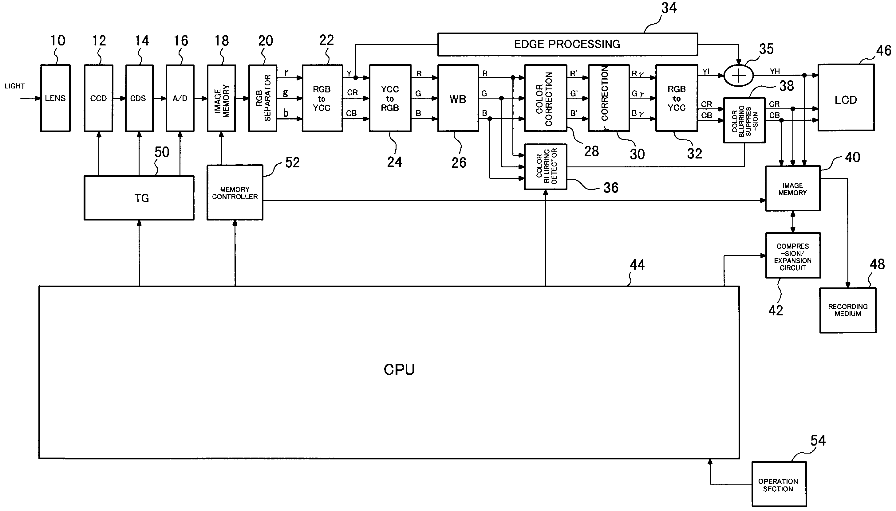
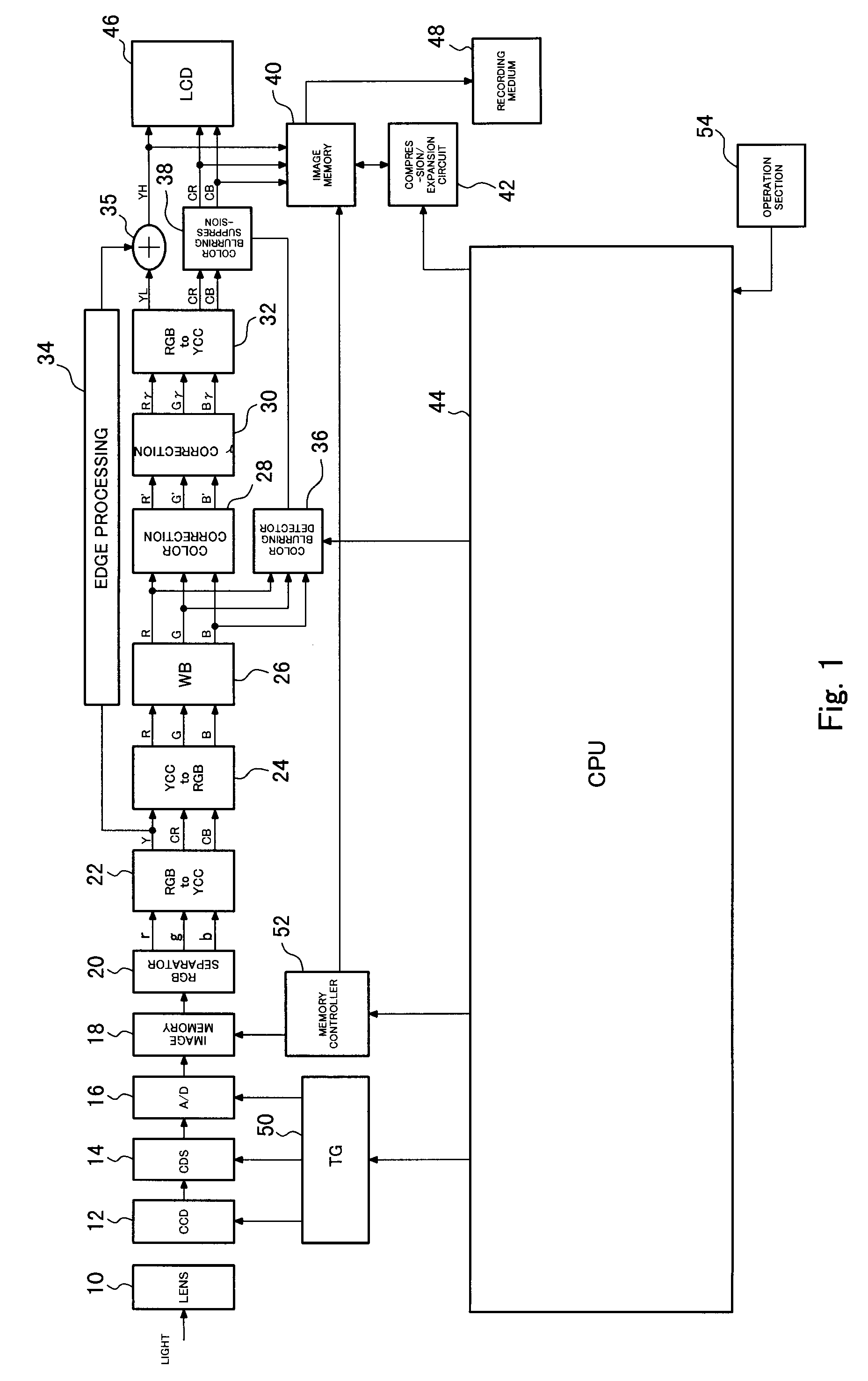
[0048]FIG. 1 is a block diagram showing the configuration of a digital camera according to a first embodiment of the present invention. A lens 10 induces light originating from a subject to form an image on a CCD 12 which acts as an imaging element. The CCD 12 has a color filter of a Bayer pattern; subjects subject light to photoelectric conversion to thereby generate an image signal; and supplies the image signal to a CDS 14. The CDS 14 subjects the image signal from the CCD 12 to correlation dual sampling and supplies the thus-sampled signal to an analog-to-digital (A / D) converter 16. The A / D converter 16 converts the image signal into a digital signal, and stores the thus-converted digital signal into image memory 18. The CCD 12, the CDS 14, and the A / D converter 16 operate in synchronism with a clock signal supplied from a timing generator (TG) 50. Reading and writing of data from and to the image memory 18 are controlled by a memory controller 52. The image signal read from the...

second embodiment

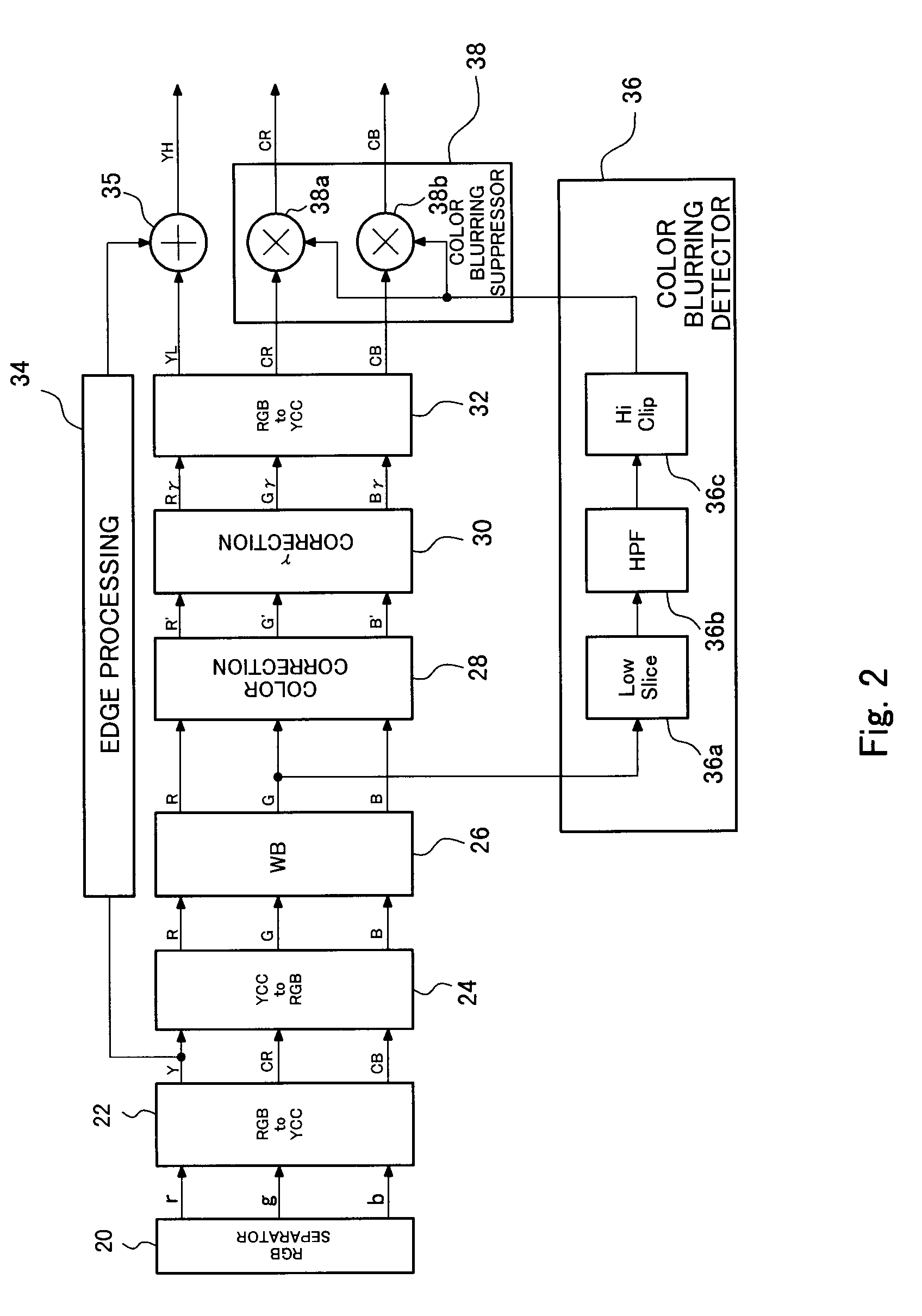
[0055]FIG. 4 shows the configuration of the color-blurring detection circuit (chromatic aberration detection circuit) 36 of a second embodiment. The color-blurring detection circuit 36 shown in FIG. 2 is additionally provided with a high clip circuit 36d and a multiplying circuit 36e. As in the case of FIG. 2, the G signal output from the white balance adjustment circuit 26 is supplied to the low slice circuit 36a, and to the high clip circuit 36d as well.

[0056]The high clip circuit 36d clips the high level of the G signal and supplies the thus-clipped signal to the multiplying circuit 36e. The clip level of the high clip circuit 36d is identical with the slice level of the low slice circuit 36a. The multiplying circuit 36e multiplies the G signal clipped by the high clip circuit 36d by the signal (see FIG. 3D) output from the high clip circuit 36c.

[0057]When color-blurring of the edge portion of highlight is suppressed, the level of the G signal sometimes does not sufficiently dec...

third embodiment

[0058]FIG. 5 shows the configuration of the color-blurring detection circuit (chromatic aberration detection circuit) 36 of a third embodiment. The color-blurring detection circuit 36 shown in FIG. 2 is additionally provided with a low slice circuit 36f, a high-pass filter 36g, a low clip circuit 36h, and an inverter 36i, all of which are intended for processing the B signal, as well as with the multiplying circuit 36e. As in the case of the circuit shown in FIG. 2, the G signal output from the white balance adjustment circuit 26 is supplied to the low slice circuit 36a, and the B signal is supplied to the low slice circuit 36f.

[0059]The low slice circuit 36f and the high-pass filter 36g have the same functions as those of the low slice circuit 36a and the high-pass filter 36b, and extract the edge portion of highlight of an input signal. The low slice circuit 36f and the high-pass filter 36g extract the edge portion of highlight of the B signal rather than the edge portion of high...


PUM


Abstract

Accurately suppress chromatic aberration arising in a subject image is described. An image signal, which is obtained by a lens and a CCD and pertains to a subject image, is subjected to white balance adjustment performed by a white balance adjustment circuit. The signal is supplied to a color-blurring detection circuit before undergoing gamma correction. The color-blurring detection circuit has a low slice circuit, a high-pass filter, and a high clip circuit; detects an edge portion of a highlight of a G signal constituting the image signal; and supplies the detected edge portion as a color-blurring detection signal to a color-blurring suppressor circuit disposed subsequent to a γ correction circuit. The color-blurring suppressor circuit corrects color-difference signals CB, CR, which have been subjected to gamma correction, by use of the color-blurring detection signal, thereby suppressing the color-blurring having arisen in the edge of a highlight of the image.

Description

FIELD OF THE INVENTION[0001]The present invention relates to a chromatic aberration suppressor circuit, and more particularly, to a technique for generating an appropriate color image by suppressing chromatic aberration, such as axial chromatic aberration, chromatic aberration of magnification, or the like.BACKGROUND OF THE INVENTION[0002]A refraction factor of light varies according to a wavelength. Light of a shorter wavelength causes great refraction, and light of a longer wavelength causes small refraction. This induces a phenomenon, called chromatic aberration, of a position (hereinafter simply called an “image formation position”), where an image is formed, being changed by the wavelength of light.[0003]For instance, in the case of a beam entering a lens from one point on an optical axis, an image formation position varies according to the wavelength of the beam. When a position where a green image is formed is taken as P, blue (B) light whose wavelength is shorter than that o...

Claims


Application Information

Patent Timeline
Patent Type & Authority Patents(United States)
IPC IPC(8): H04N5/217H04N1/40
CPCH04N5/217H04N9/045H04N5/3572H04N23/81H04N25/61H04N25/611
Inventor SAKURAI, JUNZOUMIKI, TAKANORI
Owner MONUMENT PEAK VENTURES LLC
Why Eureka
Try Eureka