
POL system architecture with analog bus

a technology of analog bus and system architecture, applied in the direction of program control, ignition automatic control, instruments, etc., can solve the problems of increasing complexity and size of the overall electronic device, requiring multiple d/a and a/d conversion stages, and inability to deliver high current at low voltage over a relatively long distan

Active Publication Date: 2009-09-01
INFINEON TECH AMERICAS CORP
View PDF12 Cites 21 Cited by
  • Summary
  • Abstract
  • Description
  • Claims
  • Application Information

AI Technical Summary

Benefits of technology

[0048]5. It is far less radical and has the best of both worlds, analog and digital. The POLs are still traditional analog circuits except for the serial digital port and D / A circuits and multiplexer circuit. The known full-digital solutions in contrast have to cope with high speed PWM, high precision A / D and very high digital clock speeds in an IC process that may not be cost effective when high voltage circuits such as drivers are integrated.

Problems solved by technology

This is problematic in that it is impractical to deliver high current at low voltages over a relatively long distance and still meet desired regulation performance.
A drawback with such control systems is that they add complexity and size to the overall electronic device by using, for example, a six bit parallel bus to operate each POL regulator and three additional wires to monitor each POL regulator.
Another issue with the digital bus is that it requires multiple D / A and A / D conversion stages, which are expensive and also introduce delay.
Further, it provides only imprecise control and monitoring of the POL regulator's functions and parameters.
Using more bits will solve the resolution problem at the expense of rapidly increased complexity and cost.
It also requires duplicated internal components for precision voltage reference, A / D, sequencing and DSP in each POL regulator, which increases their cost for systems with multiple POLs.

Method used


Image

  • POL system architecture with analog bus
  • POL system architecture with analog bus
  • POL system architecture with analog bus

Examples


Embodiment Construction

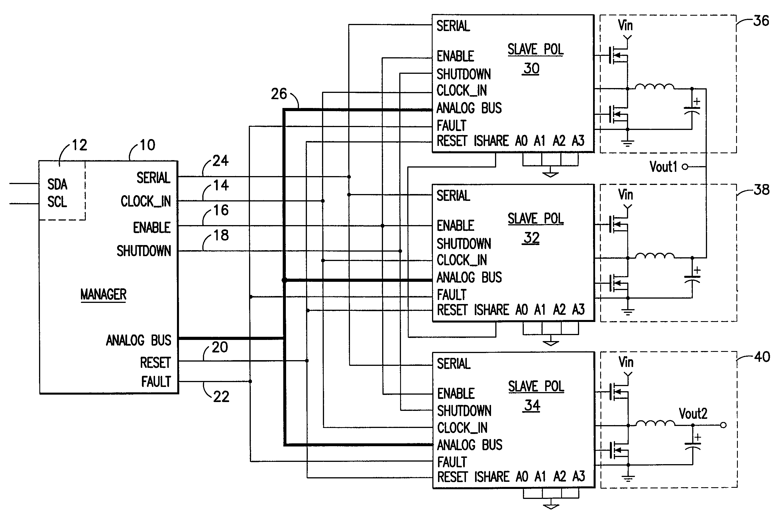
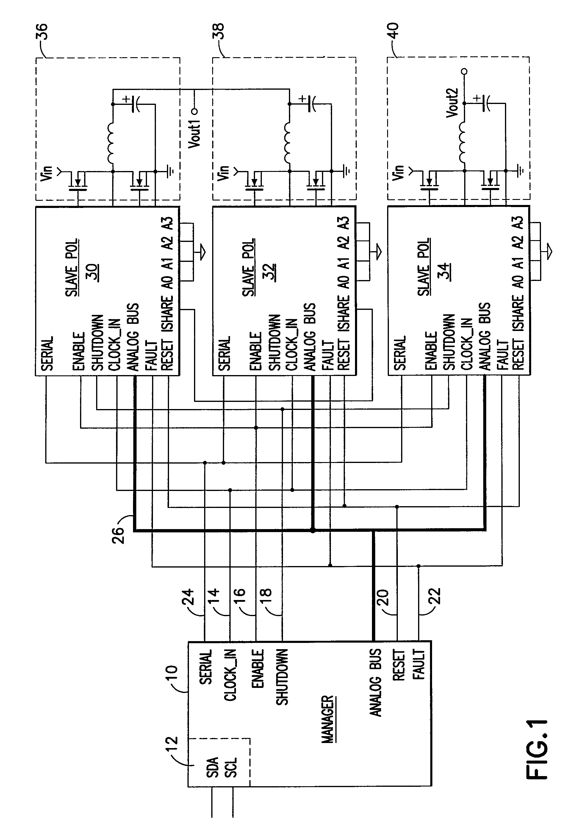
[0020]FIG. 1 is a system-level schematic diagram of the architecture according to an embodiment of the invention. A manager IC 10 is controlled externally by an I2C interface 12. Analog clock, enable, shutdown, reset and fault signals are communicated via lines 14, 16, 18, 20, 22. Addressing of the POLs is carried out over a serial digital bus 24. In this example, there are three POLs 30, 32, 34. Also linking the manager and the POLs is an analog bus 26.

[0021]As seen in FIG. 1, the specific application of the POLs in this example is to power a plurality of DC-DC buck power supply circuits 36, 38, 40.

[0022]When several POLs are connected in parallel like 30 and 32 to provide more output current, current sharing between these POLs is important, and can be achieved traditionally by having a single current sharing wire between them. Ishare represents the average output current, and each POL compares its output current against it to adjust its output current to achieve output current sha...


PUM

PropertyMeasurementUnit
output voltage set pointaaaaaaaaaa
voltagesaaaaaaaaaa

Abstract

A power control system and method including a plurality of point-of-load regulators (POL) providing corresponding regulated output voltages; a manager for communicating control signals and operational parameters with said point-of load regulators; a digital bus to carry control signals therebetween; and an analog bus to carry operational parameters therebetween. Analog sensing circuits and a mutliplexer on the POL communicate operational parameters to and from the manager via the analog bus and are controlled via the digital bus. The operational parameters include output voltage, output current, over voltage, temperature, amplifier or comparator offset, and amplifier gain. The analog sensing circuits are calibrated by trim registers on the POL under digital control by the manager.

Description

CROSS REFERENCE TO RELATED APPLICATIONS[0001]The present application is based upon and claims priority of provisional application No. 60 / 662,897, filed Mar. 17, 2005, incorporated by reference.BACKGROUND OF THE INVENTION[0002]1. Field of the Invention[0003]The present invention relates to controlling point-of-load regulators, and more particularly, to a system and method using an analog bus to communicate with point-of-load regulators.[0004]2. Related Art[0005]Point-of-load (“POL”) regulators, which are also referred to as voltage regulators or DC / DC converters, are commonly used in conjunction with electronic circuits, typically to satisfy voltage / current requirements of the electronic circuits that differ from the voltage that is readily available or the current that can practically be delivered. For example, some electronic devices only include a single voltage input (e.g., 12 v), but require different voltages for circuits contained within (e.g., 1.2 v, 3.3 v, 5 v, etc.). A comm...

Claims


Application Information

Patent Timeline
Patent Type & Authority Patents(United States)
IPC IPC(8): G06F1/26B23K11/24
CPCG05B19/0423H02M3/1584H02M3/157G05B2219/21005
Inventor ZHANG, JASON
Owner INFINEON TECH AMERICAS CORP
Learn More