Microdosing device

a microdosing device and microdosing technology, which is applied in the direction of positive displacement liquid engines, pumping machines, machines/engines, etc., can solve the problems of affecting the production cost of a microdosing device, the inability to guarantee the uniform supply of liquid in the entire dosing chamber during one dispensing operation, etc., to achieve low resistance to liquid, increase the dosing accuracy, and reduce the effect of liquid pressure build-up

Active Publication Date: 2009-09-08
APTAR RADOLFZELL
View PDF22 Cites 15 Cited by
  • Summary
  • Abstract
  • Description
  • Claims
  • Application Information

AI Technical Summary

Benefits of technology

[0006]In one embodiment of the invention, at least one storage chamber is connected to and communicates with the dosing chamber via at least one admission channel. A storage chamber is provided for temporary storage of liquid to be dispensed, in particular to make it possible to compensate for peak delivery quantities during the dispensing operation. In this way, the storage chamber also ensures further homogenization of the dispersion of the droplets and increased dosing accuracy. The storage chamber is for this purpose connected to and communicates with the dosing chamber via at least one admission channel, so that liquid stored in the storage chamber can flow directly into the dosing chamber via the admission channel. The storage chamber can be of a passive design, without its own delivery means, or of an active design, with its own delivery means. Filling of the storage chamber can take place only temporarily, in particular immediately before a dispensing operation, or can take place permanently.
[0007]In a further embodiment of the invention, the storage chamber is provided, at an end area directed away from the dosing chamber, with an equalization opening. By means of an equalization opening on the storage chamber, a pressure build-up in the storage chamber during filling with liquid is reduced or avoided. Moreover, the equalization opening makes it easier for the liquid to flow in the direction of the dosing chamber, because said equalization opening allows for pressure equalization in relation to an environment. In this way, the storage chamber has a low resistance for the liquid. A storage chamber can in particular be designed as a capillary, as a result of which particularly easy filling can be achieved through the capillary forces. Moreover, by using a capillary, it is possible in a simple manner to ensure complete filling and emptying without gas bubbles in the liquid, so that the stored liquid can be passed into the dosing chamber directly and in particular without measures for gas separation.
[0008]In a further embodiment of the invention, the equalization opening of the storage chamber is closed by a gas filter. By means of a gas filter, which can be designed in particular as a hydrophobic membrane filter, it is possible to prevent a situation where the liquid stored in the storage chamber is contaminated by microbes from an environment of the microdosing device. The gas filter is thus configured so that it allows only gas particles to pass through, while bacteria, viruses or liquid are prevented from passing through the gas filter. In this way, the gas filter can additionally be used as a means of limiting the filling of the storage chamber, since escape of the liquid from

Problems solved by technology

In the case where there is a single admission channel on the dosing chamber, as is known from the prior art, it is often not possible to guarantee uniform supply of the entire dosing chamber with liquid dur

Method used


Image

  • Microdosing device
  • Microdosing device

Examples


Embodiment Construction

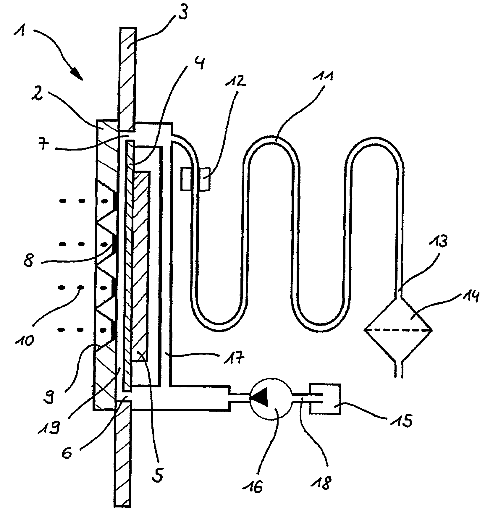
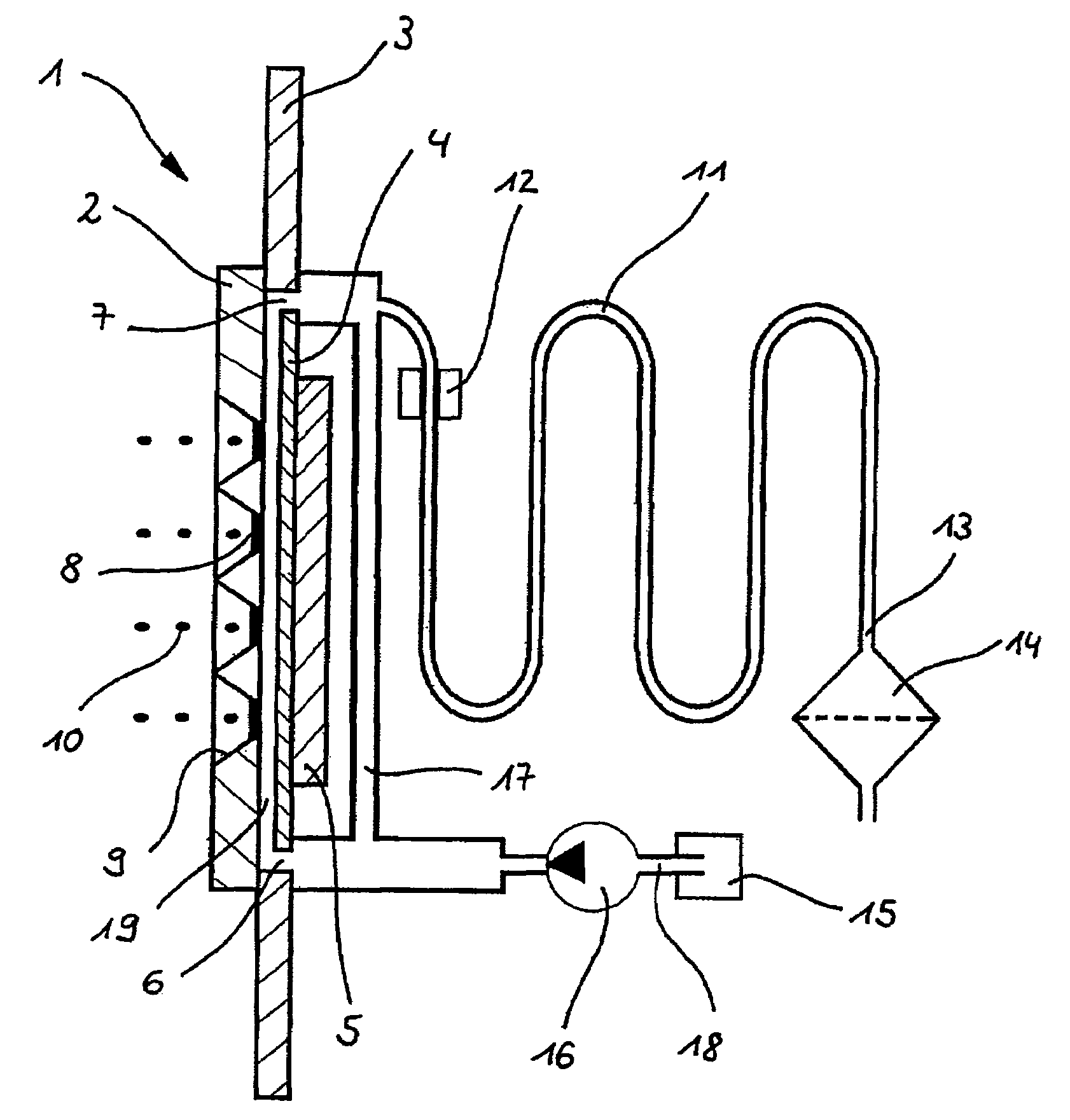
[0017]A microdosing device 1 has a dosing chamber which is designed as compression chamber 19 and which is delimited by boundary surfaces such as a membrane 2, a structural part 3 and a rear wall 4. Dispensing openings 9 designed as membrane pores 8 (not shown in detail) are provided in the membrane 2, and a liquid 10 contained at least temporarily in the compression chamber can be dispensed through these openings and into an environment of the microdosing device 1. Arranged on the rear wall 4 of the compression chamber 19 there is a vibration unit which is designed as an ultrasonic oscillator 5 and which can be powered at least temporarily, via control means (not shown in detail), with electrical energy in order to generate an oscillation. The compression chamber 19 is also provided with a number of admission channels, of which one is embodied as a direct inflow 6 and another as a reservoir inflow 7. While the direct inflow 6 is coupled directly to a filling means 16, the reservoir...


PUM


Abstract

A microdosing device includes a dosing chamber which at least temporarily receives a quantity of liquid, and to which at least one dispensing opening is assigned. A vibration unit is operatively connected to at least one boundary surface of the dosing chamber in order to cause this boundary surface to oscillate for the purpose of a dispensing operation.
At least two admission channels spaced apart from one another are provided on the dosing chamber.

Description

FIELD OF THE INVENTION[0001]The invention relates to a microdosing device with a dosing chamber which at least temporarily receives a quantity of liquid and to which at least one dispensing opening is assigned, and with a vibration unit which is operatively connected to at least one boundary surface of the dosing chamber in order to cause this boundary surface to oscillate for the purpose of a dispensing operation.BACKGROUND OF THE INVENTION[0002]Microdosing devices for dispensing small and very small droplets are known from cosmetic or pharmaceutical medium dispensers, such as inhaler devices for liquid medical substances. These have a dosing chamber which can be filled from a medium reservoir with a quantity of liquid and which has at least one dispensing opening through which the liquid can escape after a flow resistance has been overcome. The flow resistance is determined in particular by the size, geometry and material of the dispensing opening and by a surface tension and a vi...

Claims


Application Information

Patent Timeline
IPC IPC(8): B05B1/08A61M11/00B05B1/30B05B17/04B05B17/06B05B9/00B05C1/00B41J2/045A61M5/142A61M15/00F04B43/04
CPCA61M15/0065A61M15/0085F04B43/043B05B17/0676B05B17/0638
Inventor KOERNER, JOACHIMHELMLINGER, MICHAELSCHUERLE, HOLGER
Owner APTAR RADOLFZELL
Why Eureka
Try Eureka