
X-ray examination apparatus

a technology of x-ray examination and x-ray, which is applied in the direction of electrical apparatus, medical science, diagnostics, etc., can solve the problems of limited patient coverage, inability to inspect the whole body of the patient, and more limited regarding supported inspection angles, so as to achieve good patient coverage and not limit the rotational freedom of the apparatus

Inactive Publication Date: 2009-09-08
KONINK PHILIPS ELECTRONICS NV
View PDF18 Cites 16 Cited by
  • Summary
  • Abstract
  • Description
  • Claims
  • Application Information

AI Technical Summary

Benefits of technology

The present invention provides an improved X-ray examining apparatus that can provide good patient coverage while still allowing the apparatus to rotate freely. The apparatus includes a main curved arm, a first auxiliary arm, and a second auxiliary arm. The first auxiliary arm carries one radiation module and the second auxiliary arm carries another radiation module. The first auxiliary arm has a shape that complements the curvature of the main curved arm at least at its first end section and can be moved in relation to this end section at least in a direction away from it. The second auxiliary arm is also movable in a direction inwards along its end section. The apparatus allows for a wide range of inspection angles and a good patient coverage without limiting the rotational freedom of the apparatus. The apparatus is compact, flexible, and easy to use.

Problems solved by technology

This is quite a challenge.
This C-shaped system allows large rotation angles but is however normally limited regarding patient coverage, i.e. it is normally not possible to inspect the whole body of the patient without moving the patient.
This arc allows better patient coverage but is however more limited regarding supported inspection angles.
However these add-on elements limit the rotational freedom of the C-shaped arc.

Method used


Image

  • X-ray examination apparatus
  • X-ray examination apparatus
  • X-ray examination apparatus

Examples


Embodiment Construction

[0036]The present invention is generally directed towards an X-ray examination apparatus using X-ray radiation for inspecting the body of a patient. In the following an apparatus will be described having a C-shaped main arm or arc. It should however be realized that the present invention can be used with other configurations of the main arm, like for instance a G-shaped arm as long as at least the main arm moves around an isocentre.

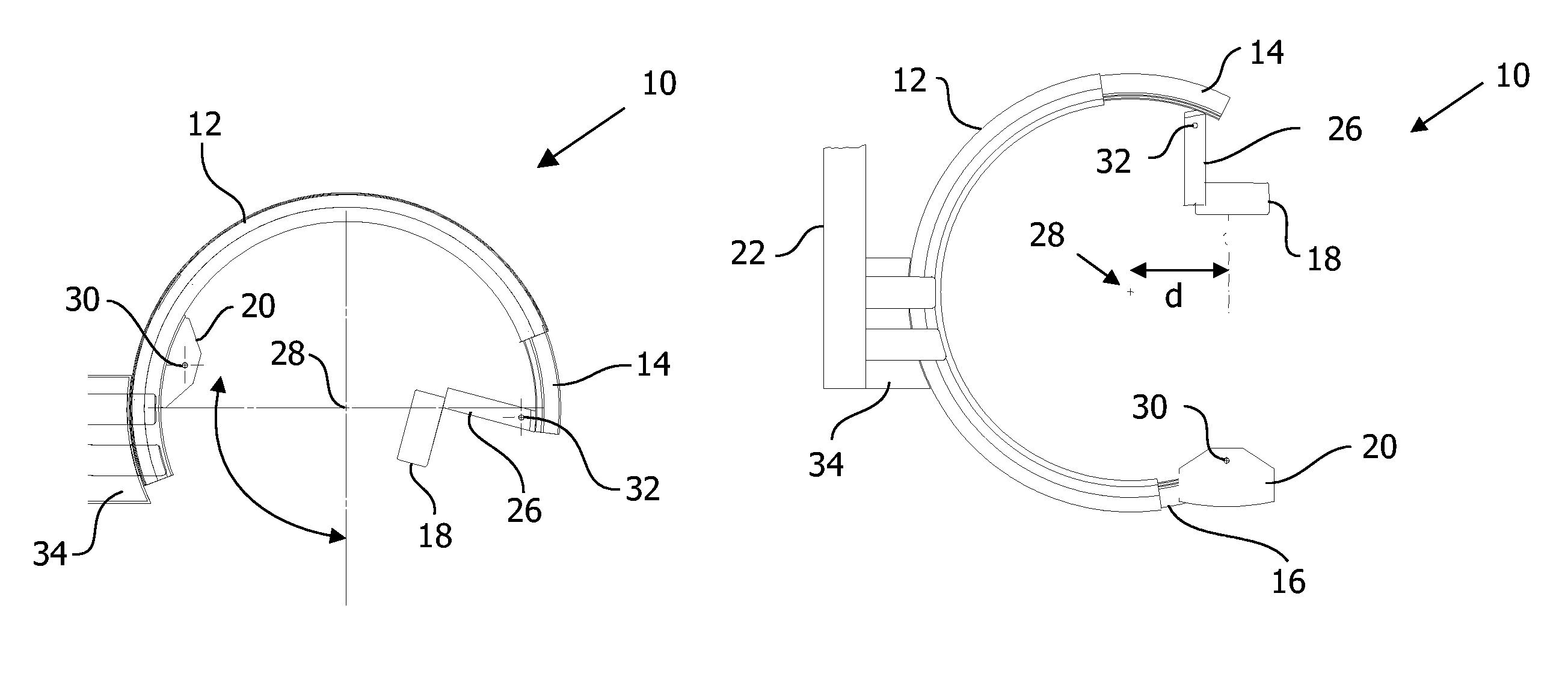
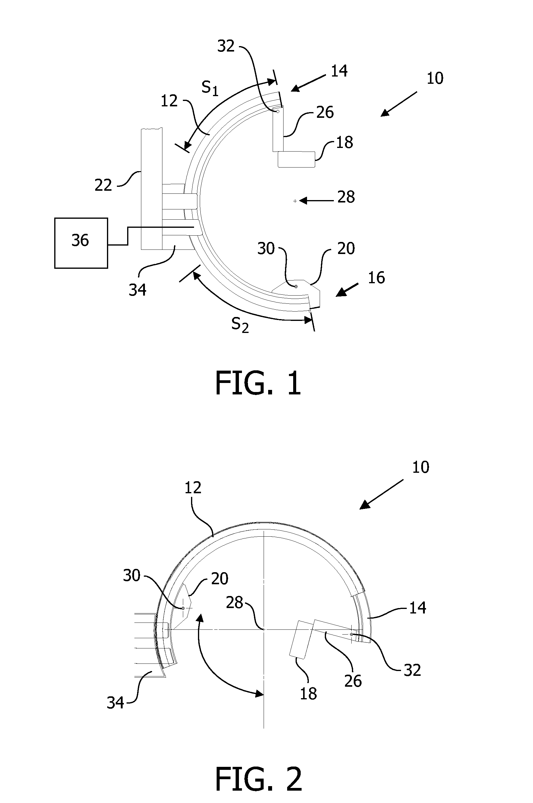
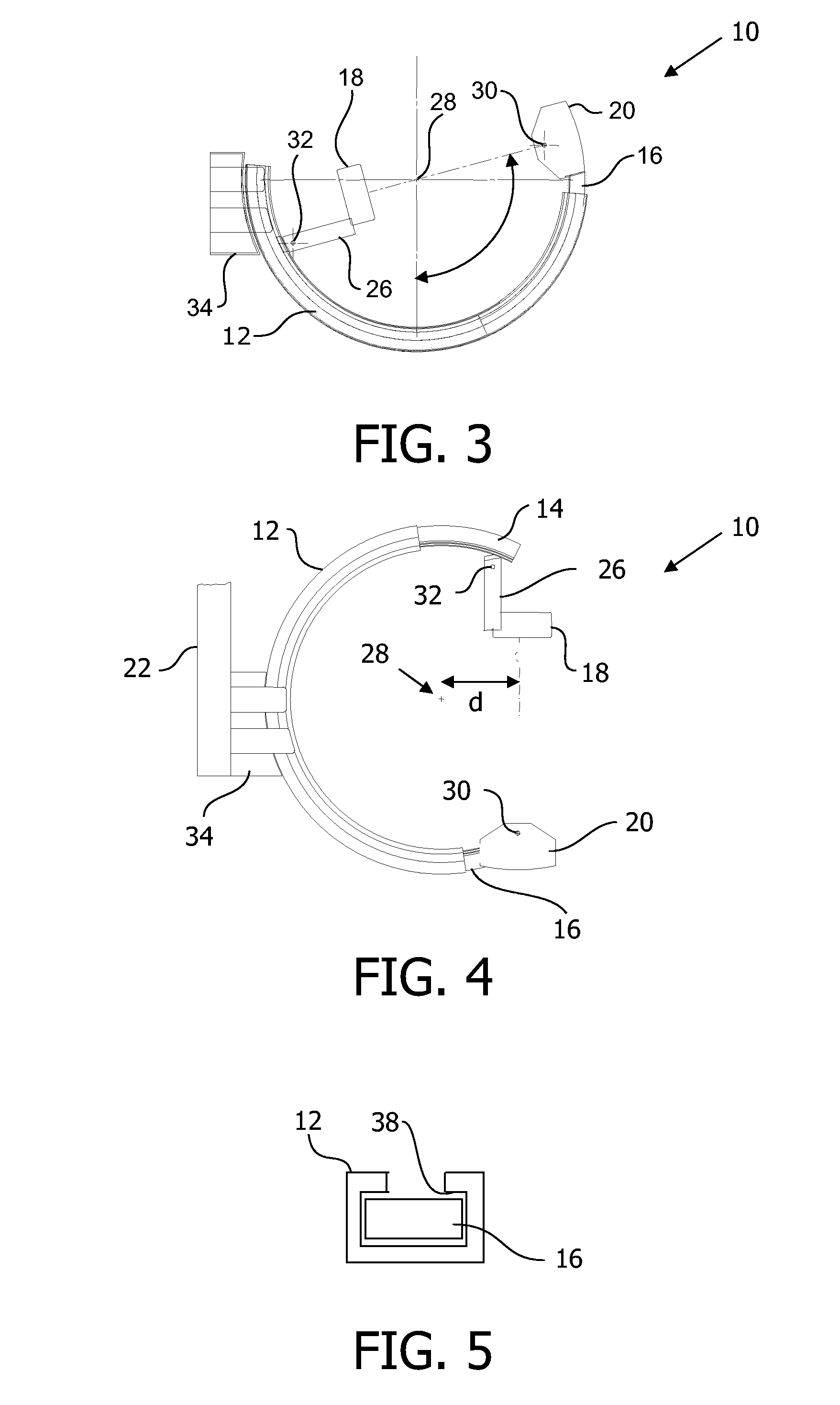
[0037]FIG. 1-4 show side views of an apparatus 10 according to a first embodiment of the present invention in different positions. In these drawings there is provided a main curved arm 12, which is here shaped as half a circle or a C. The main arm 12 is furthermore fastened to a holder 22, which includes a curved first guiding system 34 that can turn the main arm 12 round an isocentre 28 defined by the curvature of the first guiding system 34. The main arm is in this way rotated round a first rotational axis provided by the first guiding system. This firs...


PUM


Abstract

An X-ray examination apparatus (10) comprises radiation modules in the form of an X-ray source (20) and an X-ray detector(18), a main curved arm (12) having opposite end sections (S1, S2) and a first auxiliary arm (14) provided at one end section (S1) of the main arm. The first auxiliary arm carries one radiation module (18) and another radiation module (20) is coupled to the other end section of the main arm. The first auxiliary arm has a shape that complements the curvature of the main curved arm at least at the first end section and is movable with respect to this end section at least in a direction away from it. In this way a wide range of inspection angles as well as a good patient coverage is achieved without limiting the rotational freedom of the apparatus.

Description

TECHNICAL FIELD[0001]The present invention is generally related to the field of medical inspection devices. The present invention is more particularly directed towards an X-ray examination apparatus comprising a main curved arm.BACKGROUND OF THE INVENTION[0002]In the field of X-ray examining apparatuses for inspecting the bodies of patients, there are continuous efforts being made for designing the examining apparatuses to allow the coverage of as much of the body as possible and to provide as wide angles of inspection of the body as possible. This does also have to be combined with an ergonomically well functioning apparatus for the staff handling it. This means that the medical staff should be able to easily access the patient in order to for instance perform operations while at the same time not having to change the position of the patient when inspections of the patient are to be made from various angles. This is quite a challenge.[0003]In doing this there have been a number of ...

Claims


Application Information

Patent Timeline
Patent Type & Authority Patents(United States)
IPC IPC(8): H05G1/02
CPCA61B6/4441
Inventor TIMMERMANS, ROGER ANTON MARIELAFARRE, RAYMOND WILHELMUS LOUIS
Owner KONINK PHILIPS ELECTRONICS NV
Learn More