Axial flow fan

a technology of axial flow and fan blades, which is applied in the direction of vessel construction, bridges, other chemical processes, etc., can solve the problems of difficult to achieve satisfactory air blowing efficiency and noise reduction, and difficulty in reducing noise occurring during the rotation of axial flow, so as to prevent blade deformation, promote structural stability, and high efficiency

Inactive Publication Date: 2009-09-08
HANON SYST
View PDF4 Cites 9 Cited by
  • Summary
  • Abstract
  • Description
  • Claims
  • Application Information

AI Technical Summary

Benefits of technology

[0015]Accordingly, the present invention has been made keeping in mind the above problems occurring in the prior art, and an object of the present invention is to provide an axial flow fan which prevents the deformation of blades even when rotated at high speed, thus promoting structural stability, and which achieves high efficiency and satisfactory capacity despite a low rotational frequency.

Problems solved by technology

However, it has been well-known that it is very difficult to achieve satisfactory air blowing efficiency and noise reduction.
As a result, there is difficulty in reducing noise occurring during the rotation of the axial flow fan 10b.

Method used


Image

  • Axial flow fan
  • Axial flow fan
  • Axial flow fan

Examples


Embodiment Construction

[0035]The features and advantages of the present invention will be more clearly understood from the following detailed description. Terms and words used in the specification and claims must be regarded as concepts selected by the inventor as the best method of illustrating the present invention, and must be interpreted as having meanings and concepts adapted to the scope and sprit of the present invention to understand the technology of the present invention.

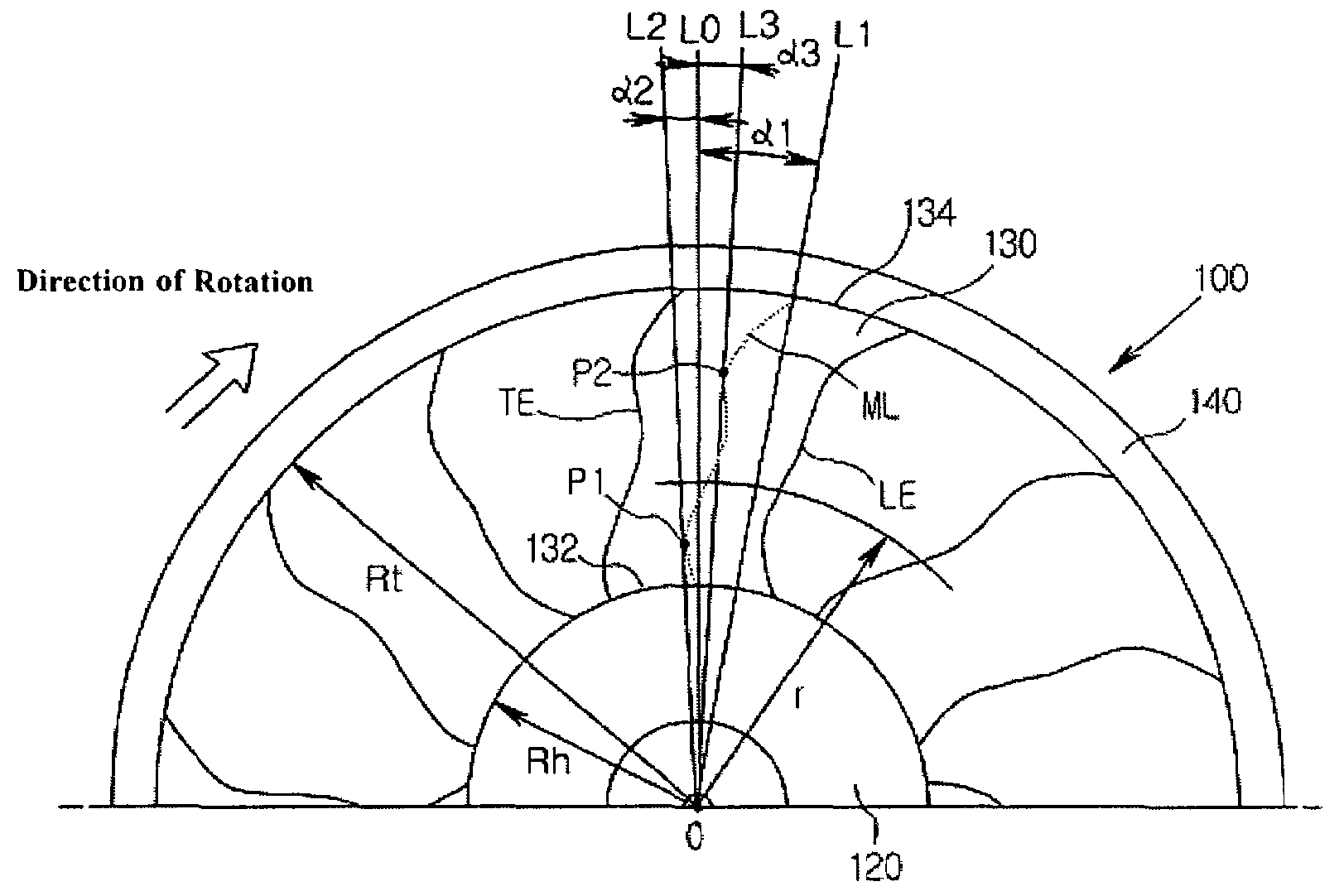
[0036]With reference to FIG. 8, in the present invention, a leading edge (LE) of a blade 130 denotes an edge of the blade 130 in a rotational direction. A trailing edge (TE) of the blade 130 denotes an edge of the blade 130 in a direction opposite the rotational direction. A chord length (CL) of the blade 130 denotes a length from the leading edge (LE) to the trailing edge (TE) of the blade 130 at the same radius (see, FIG. 4). A mid-chord line (ML) denotes a line connecting middle points between the leading edge (LE) and the tr...


PUM


Abstract

Blades mounted on a circumferential outer surface of a hub of an axial flow fan do not deform even when rotated at high speed, thus promoting structural stability. The direction of the sweeping angle of each blade alternately changes between the blade root and tip. A chord length between the blade leading and trailing edges gradually decreases from the blade root to an intermediate portion of the blade, and the chord length gradually increases from a predetermined position on the intermediate portion of the blade to the blade tip.

Description

RELATED APPLICATION[0001]The present application is based on, and claims priority from, KR Application Number 2004-018645, filed Mar. 19, 2004, the disclosure of which is hereby incorporated by reference herein in its entirety.BACKGROUND OF THE INVENTION[0002]1. Field of the Invention[0003]The present invention relates generally to axial flow fans and, more particularly, to an axial flow fan which prevents deformation of blades even when rotated at high speed, thus promoting structural stability, and which achieves high efficiency and satisfactory capacity despite a low rotational frequency.[0004]2. Background of the Related Art[0005]As well known to those skilled in the art, axial flow fans are used to cool a heat exchanging medium circulating in, for example, a heat exchanger of a vehicle, such as a radiator or a condenser. As shown in FIG. 1, such an axial flow fan 10 includes a hub 20 which is coupled to an output shaft 52 of a drive unit 50 such as a motor, a plurality of blade...

Claims


Application Information

Patent Timeline
Patent Type & Authority Patents(United States)
IPC IPC(8): F04D29/38F04D29/32
CPCF04D29/326F04D29/384Y10S416/05Y10S416/02E01D22/00E01D19/041E01D19/047E01D19/14E01D2101/32
Inventor PARK, SE-YOUNGCHO, KYUNG-SEOK
Owner HANON SYST
Why Eureka
Try Eureka