
Wire cloth, in particular paper making wire cloth

a wire cloth and paper making technology, applied in the field of paper making wire cloth, can solve the problems of inability to accept the type of joining of layers, limited wear potential, and cracks in seams or wire cloths in use, and achieve the effects of improving the design of wire cloths, good flexural stiffness values, and high dewatering performan

Active Publication Date: 2009-09-08
ANDRITZ TECH & ASSET MANAGEMENT
View PDF8 Cites 4 Cited by
  • Summary
  • Abstract
  • Description
  • Claims
  • Application Information

AI Technical Summary

Benefits of technology

[0009]An object of the present invention is to provide an improved the wire cloth design, while maintaining the advantages of the prior art designs, such that especially in the field of producing sanitary paper very high dewatering performance and fiber support are provided. At the same time, the fabric should be thin, but nevertheless mechanically stable against washboard marks and distortion, and should still have good flexural stiffness values in the transverse direction and ensure the possibility of advantageous seaming for joining the ends of the wire cloth.
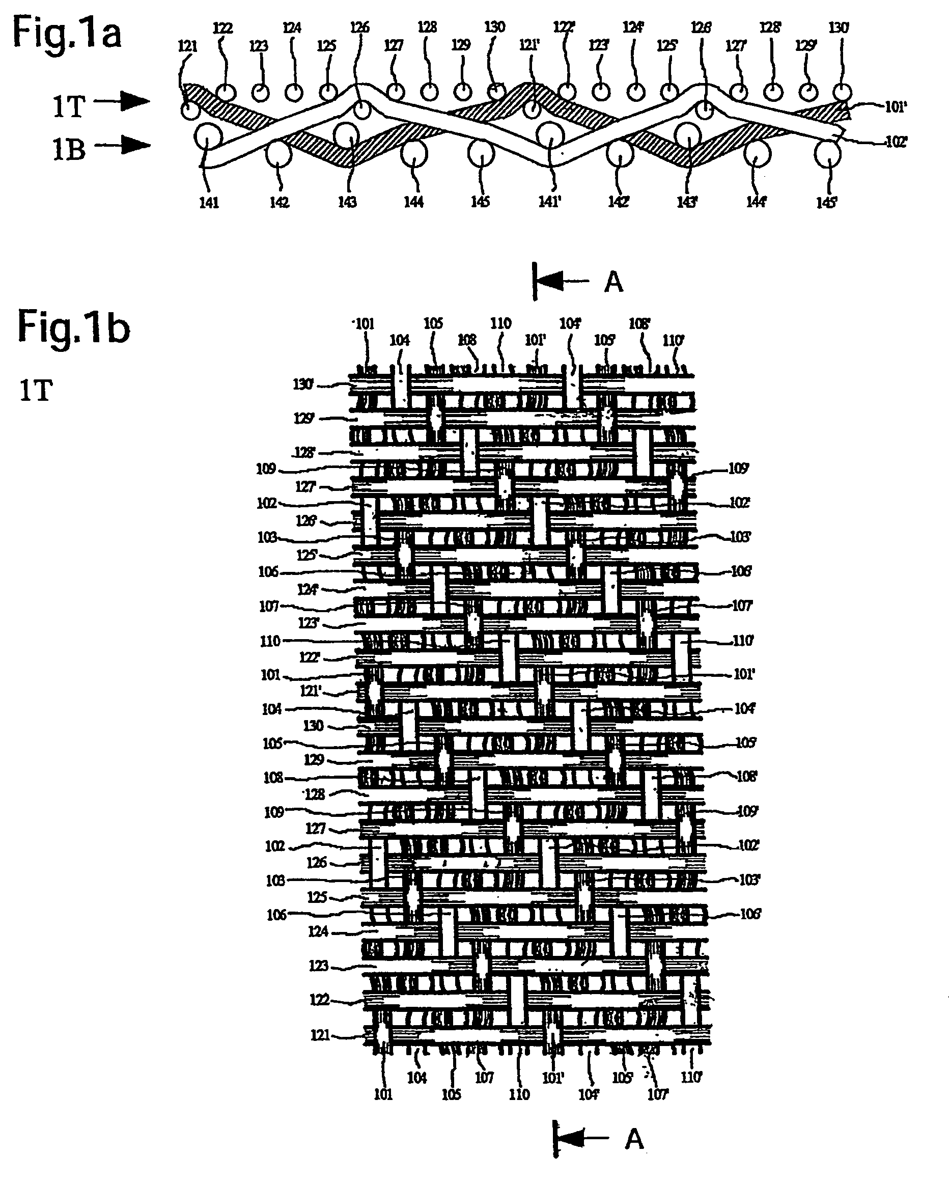
[0010]This object is basically achieved by a wire cloth, where the wire bridges of the upper cross direction wires extend within a pattern repeat at least over nine making direction wires and at most under one making direction wire. Because the wire bridges of the lower cross direction wires within a pattern repeat extend at least under six and over at least two making direction wires, and because between two making direction wires extending over a cross direction wire at least one other making direction wire extends under the same cross direction wire, on the upper or paper side the long wire bridges necessary for good fiber support are obtained from cross direction wires which in conjunction with the open warp ensures the required permeability for the required high dewatering performance. In addition to better fiber support, the long wire bridges act advantageously with respect to bending stability in the transverse direction of the wire cloth. The bottom or machine side, due to the double binding of the lower cross direction wires, ensures high stability with respect to diagonal distortion. Moreover, high wear resistance in the papermaking machine is achieved by the lower cross direction wires extending under at least six making direction wires.
[0011]If the wire cloth is built up preferably from plastic filaments during production or then thermofixed, the applied tension in the direction the machine runs results in that the two binding making direction wires at the binding point move toward each other. In this way, such binding making direction wires additionally enlarge the open areas of the wire cloth. Thus, on the one hand, the permeability increases and, on the other, the lower cross direction wire is more strongly bent and continues to protrude from the lower or machine side. In this way, the lower cross direction wire can be to a larger extent “ground down” in the papermaking machine. In one preferred embodiment of the wire cloth of the present invention, the top and bottom sides are formed from the same number of making direction wires, without needing to be any fixed assignment of individual making direction wires to one of the two sides. The number of cross direction wires on the top or paper side is higher than on the bottom or machine side.

Problems solved by technology

Often, decreasing fibrous material retention favors high dewatering performance since the long wire bridges of the cross direction wires necessary for retention are not sufficiently available.
In the known solution, currently unacceptable marking caused by the type of joining of the layers often occurs.
The wear potential is limited, i.e., the machine side formed largely by the making direction wires is exposed directly to wear and, as a result, seam or wire cloth cracks can occur in use.
The flexural stiffness in the transverse direction is limited due to the four-strand machine side and automatic seaming which is difficult to manage and which is caused by the lower making direction threads running parallel.

Method used


Image

  • Wire cloth, in particular paper making wire cloth
  • Wire cloth, in particular paper making wire cloth
  • Wire cloth, in particular paper making wire cloth

Examples


Embodiment Construction

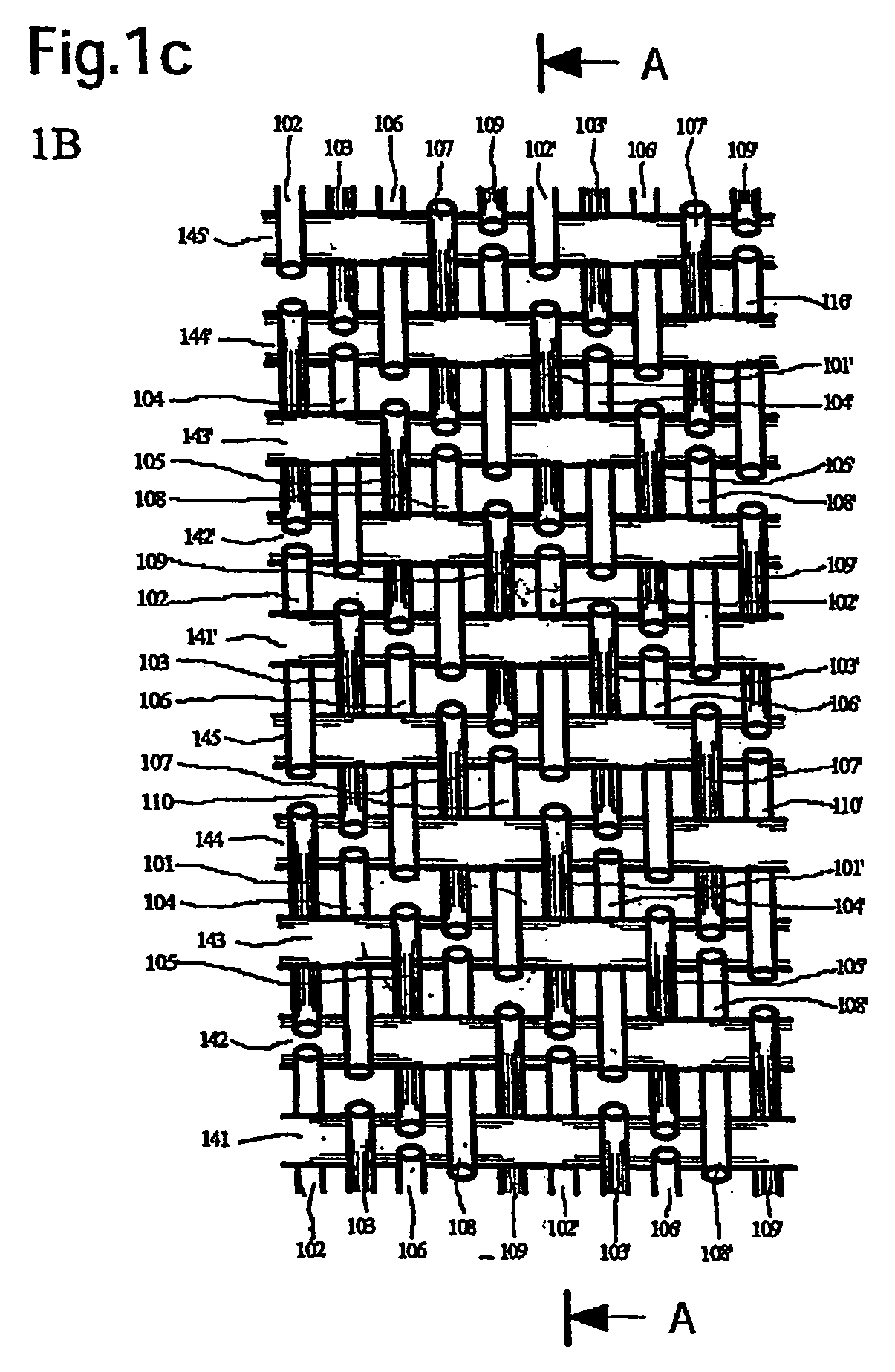
[0027]The wire cloth shown in FIGS. 1a, 1b, 1c in the form of the papermaking wire cloth implements the fabric, according to a first exemplary embodiment of the present invention, with a ratio of cross direction wires from the top (121 to 130) to the bottom (141 to 145) of 2:1. The joining of the two fabric layers 1T and 1B is by the replacement of two directly adjacent making direction wires 101 to 110 used as a functional pair. In this connection the following making direction wires can be regarded as pairs, specifically 101, 102; 103, 104; 105, 106; 107, 108, and 109 and 110. The reference numbers having an apostrophe, that is, for example 101′ instead of 101, this means that the following repeat is being addressed.

[0028]The second exemplary embodiment of the present invention shown in FIGS. 2a to 2c relates to a papermaking wire cloth described comparably to the first embodiment, by the altered configuration of the tying sites of the making direction wires 201 to 210 on the top....


PUM


Abstract

A wire cloth, in particular a paper making wire cloth, has at least two fabric layers (1B, 1T; 2B, 2T), including an upper fabric layer made of wires in the making direction (101, 110) and wires in the cross direction (121, 130), and a lower fabric layer made of wires in the making direction and wires in the cross direction (141, 145). Wire bridges are formed for the individual fabric layers in such a way that they extend over a predeterminable distance within a pattern repeat without being tied to other wires. The wire bridges of the upper cross direction wires extend within a pattern repeat over at least nine making direction wires and under maximum one making direction wire. The wire bridges of the lower cross direction wires extend within the pattern repeat at least under six and over two making direction wires. Between two making direction wires extending over a cross direction wire, at least one other making direction wire extends under the same cross direction wire.

Description

FIELD OF THE INVENTION[0001]The present invention relates to wire cloth, in particular paper making wire cloth, having at least two fabric layers. The upper fabric layer is formed from making direction wires and from cross direction wires. The lower fabric layer is formed from making direction wires and from cross direction wires. For individual fabric layers, wire bridges are formed such that they do not have any binding to other wires over a definable path extension within a pattern repeat.BACKGROUND OF THE INVENTION[0002]The dewatering of the fibrous material suspension applied to the wire cloth from above by filtration acquires major importance in papermaking processes. The fibrous material suspension is a mixture of suitable fibers, fillers, auxiliary chemical agents, and water which forms most of the mixture. In the paper industry, this filtration process is often also called sheet formation, and takes place in the wet or sheet forming part of the papermaking machine.[0003]To ...

Claims


Application Information

Patent Timeline
Patent Type & Authority Patents(United States)
IPC IPC(8): D21F1/10D03D3/04D21F1/00
CPCD21F1/0036D21F1/00
Inventor HEGER, WOLFGANGFICHTER, KLAUS
Owner ANDRITZ TECH & ASSET MANAGEMENT
Learn More