High performance motor and magnet assembly therefor
What is AI technical title?
AI technical title is built by Patsnap AI team. It summarizes the technical point description of the patent document.
a magnet assembly and high-performance technology, applied in the field of motors, can solve the problems of increasing the overall weight and size of the stage, size and weight, and increasing the force output to moving mass ratio of the motor incorporating the magnet assembly, and achieves the effect of reducing leakage flux, high performance, and improving the force output to moving mass ratio of the motor
Inactive Publication Date: 2009-09-08
ANORAD
View PDF15 Cites 28 Cited by
Summary
Abstract
Description
Claims
Application Information
AI Technical Summary
This helps you quickly interpret patents by identifying the three key elements:
Problems solved by technology
Method used
Benefits of technology
Benefits of technology
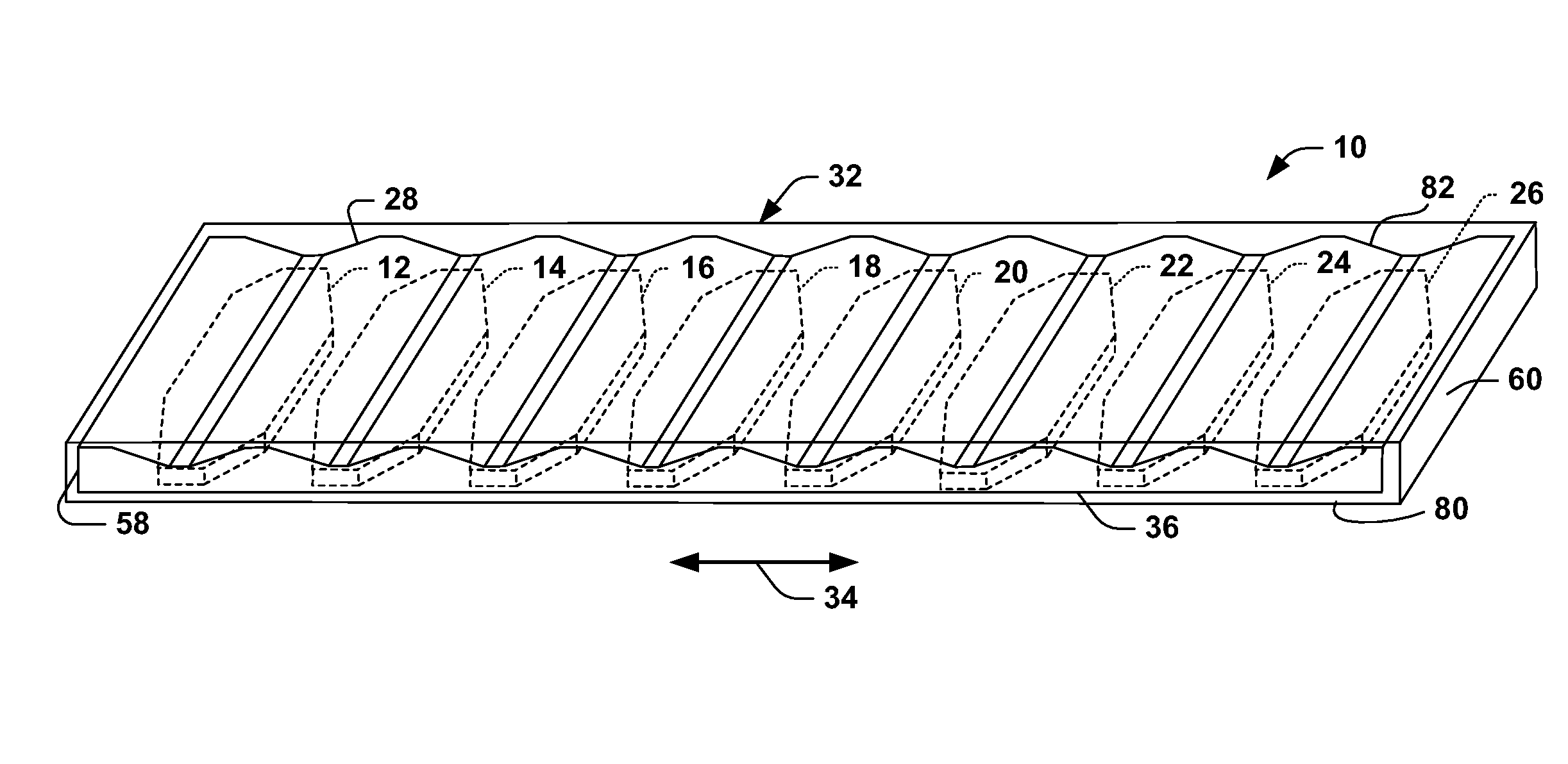
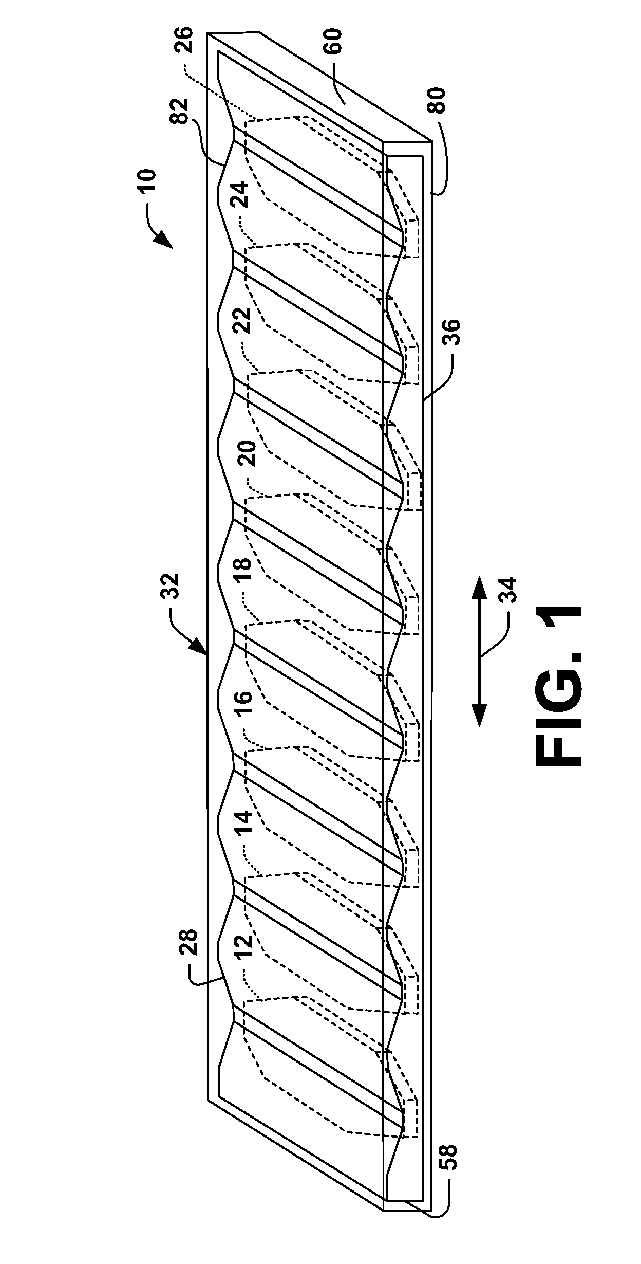
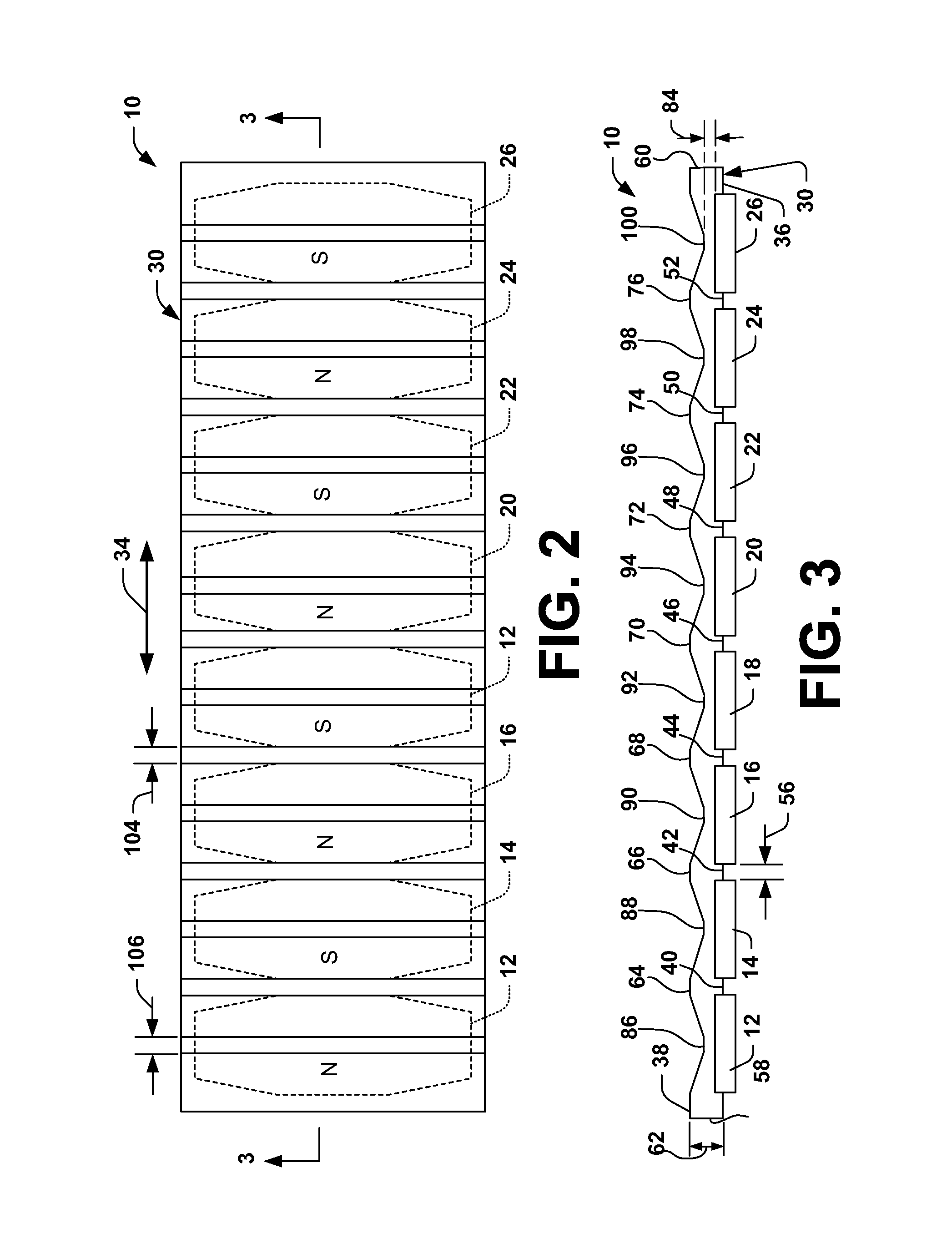
[0009]One aspect of the present invention provides a magnet assembly that can be employed as part of a linear motor stage to form a high performance linear motor. The magnet assembly includes a plurality of magnets operatively associated with magnetically conductive plate, commonly known as a back iron. The magnets extend from a common side of the back iron. The back iron is dimensioned and configured to substantially conform to magnetic flux that travels through the back iron when the magnet assembly is exposed to a magnetic field, such as from windings of a motor path. In one particular aspect of the present invention, a cross-sectional dimension of the back iron varies between opposed ends of the back iron as a function of the position and / or orientation of the magnets. For example, a thickness of the back iron is greater at locations between adjacent pairs of the magnets than at locations generally centered with the respective magnets. As a result of such back iron geometry, force output to moving mass ratio of a motor incorporating the magnet assembly is improved over conventional configurations of magnet assemblies. Also, the back iron geometry reduces leakage flux.
[0010]Another aspect of the present invention provides a linear motor system that includes a path having a plurality of windings, which can be energized to produce desired magnetic fields. The linear motor system also includes a magnet assembly, such as described above. The linear motor system achieves high performance because the magnet assembly has a reduced mass, which substantially conforms to magnet flux lines that travel through the magnet assembly during energization of path windings. The mass further can be reduced by employing generally elongated octagonal magnets, such as by removing corner portions from rectangular magnets.
[0011]According to yet another aspect, a magnet assembly can be used in a linear motor arrangement in such a way so as to generate a Halbach array. A Halbach array can be achieved by a special formation of magnets using 90-degree angles to direct each individual magnet's field in alternating vertical and horizontal orientations, such that half of the magnets are vertically polarized (e.g., perpendicular to a direction of motion of the linear motor), while the other half of the magnets are horizontally polarized, permitting maximization of the magnetic field produced thereby in a desired direction. Additionally, remnant fields that do not contribute to force output in a horizontal direction can be cancelled. This magnet arrangement can be formed as a reduced mass magnet assembly as described above, and can further concentrate magnetic flux in a desired direction while simultaneously mitigating the effects of stray magnetic fields.
[0012]According to another aspect, a platen and forcer system is provided. The system employs the reduced mass magnet assembly as previously described. Additionally or independently, other features of the forcer system are modified so as to further optimize magnetic flux capacity in a desired direction. For example, the system can comprise magnetically conductive backing materials fashioned from solid stock, laminations, and / or combinations of smaller stock, or by other known means, such as as sintering, etc., with a varied cross-sectional thickness comprising peaks and valleys, and a plurality of magnets associated therewith such that the center of each magnet is generally aligned with a valley (e.g., a relatively thinner region of the metal backing). The plurality of magnets can be arranged to generate a Halbach array that maximizes output force in a desired horizontal direction and minimizes and / or cancels magnetic fields that do not contribute to force output in the desired horizontal direction. Furthermore, the platen and forcer system mitigates shielding requirements when employed in conjunction with the Halbach array magnet arrangement, making the system highly suitable for manufacturing applications such as e-beam lithography, focused ion beam systems, and the like. For instance, an electron beam employed to etch, inspect, and / or otherwise fabricate a semiconductor wafer can be adversely affected by stray static and alternating magnetic fields, which results in intricate shielding requirements and its complex design when traditional platen and forcer systems are employed. To mitigate a need for elaborate shielding, the subject systems and methods can employ the Halbach magnet arrangement, which can facilitate reducing costs and improving throughput in such fabrication environments. It will be appreciated that any type of linear motor (e.g., iron core motors, ironless motors, can be utilized in conjunction with the various aspects set forth herein.
Problems solved by technology
The high performance systems often require moving elements subjected to high acceleration levels.
Although an inclined angle of the magnets can reduce some cogging, it presents a disadvantage in that a larger area typically must be covered by the rectangular magnets in order to sufficiently cover and interact with the coils of the armature.
This tends to increase the overall weight and size of the stage.
Such increases in size and weight can present additional obstacles, such as in applications where there are size constraints and low mass is desirable.
For example, as the mass of the stage increases, the available acceleration experiences a corresponding reduction, and the ability to stop the motor accurately also reduces because of the increased power dissipation needed to stop the motor.
Method used
Image
Click on the blue label to locate the original text in one second.
Reading with bidirectional positioning of images and text.
Examples
Embodiment Construction
[0028]The present invention provides a magnet assembly for use in a linear motor. The magnet assembly includes a back iron and an array of magnets. The back iron is in the form of a plate having opposed surfaces of the back iron. The magnets are arranged in a generally linear array along one of the surfaces. The other surface of the back iron plate is dimensioned and configured according to the magnetic field distribution and / or localized regions of saturation associated with the motor geometry / topology. For example, the surface of the back iron plate opposite to which the magnets are attached can be scalloped, such that a dimension between the opposed surfaces at locations generally aligned with the magnet centers is less than a dimension between the opposed surfaces at locations between adjacent magnets.
[0029]Additionally, the subject invention can be employed in conjunction with a rotary motor, a platen and forcer arrangement, and / or any other suitable arrangement in which the va...
PUM
Abstract
A magnet assembly includes a back iron and an array of magnets. The back iron is in the form of a plate having opposed surfaces. The magnets are arranged along one of the surfaces, with the other surface being dimensioned and configured according to the magnetic field distribution associated with the magnets. The back iron geometry provides for reduced mass, reduced leakage flux, and high flux densities to improve performance of a linear motor that employs such a magnet assembly. Additionally, the back iron can be a magnetically conductive annular ring, such as is employed in a rotary motor. Moreover, the magnets can be arranged in a manner that generates a Halbach array to increase force output in a desired direction while canceling stray magnetic fields in other directions. Similar reduced-mass designs can be employed in conjunction with a back iron of a fixed cross-section and magnets of variable thicknesses, variable lengths, and / or variable widths. In a case where the arrangement is employed in a platen and forcer system, plates on both the platen and forcer may be scalloped to reduce mass.
Description
CROSS REFERENCE TO RELATED APPLICATIONS[0001]This application is a divisional of U.S. patent application Ser. No. 11 / 381,648, filed May 4, 2006, entitled HIGH PERFORMANCE MOTOR AND MAGNET ASSEMBLY THEREFOR, which is a continuation-in-part of U.S. patent application Ser. No. 11 / 151,152, filed Jun. 13, 2005, entitled HIGH PERFORMANCE LINEAR MOTOR AND MAGNET ASSEMBLY THEREFOR, which issued as U.S. Pat. No. 7,145,271, on Dec. 5, 2006, which is a divisional application of U.S. patent application Ser. No. 10 / 889,384, filed Jul. 12, 2004, entitled HIGH PERFORMANCE LINEAR MOTOR AND MAGNET ASSEMBLY THEREFOR, issued as U.S. Pat. No. 6,919,653, on Jul. 19, 2005, which is a divisional application of U.S. patent application Ser. No. 10 / 369,161, filed Feb. 19, 2003, entitled HIGH PERFORMANCE LINEAR MOTOR AND MAGNET ASSEMBLY THEREFOR, which issued as U.S. Pat. No. 6,803,682, on Oct. 12, 2004, which claims the benefit of U.S. Provisional Patent Application Ser. No. 60 / 358,654, filed on Feb. 21, 200...
Claims
Application Information
Patent Timeline
Application Date:The date an application was filed.
Publication Date:The date a patent or application was officially published.
First Publication Date:The earliest publication date of a patent with the same application number.
Issue Date:Publication date of the patent grant document.
PCT Entry Date:The Entry date of PCT National Phase.
Estimated Expiry Date:The statutory expiry date of a patent right according to the Patent Law, and it is the longest term of protection that the patent right can achieve without the termination of the patent right due to other reasons(Term extension factor has been taken into account ).
Invalid Date:Actual expiry date is based on effective date or publication date of legal transaction data of invalid patent.

