Electric power conversion apparatus for plural DC voltage sources and an AC electrical load

a technology of a power conversion apparatus and an ac electrical load, which is applied in the direction of process and machine control, battery/fuel cell control arrangement, instruments, etc., can solve the problems of power loss, increase in the size of the whole system including the power supply, etc., and achieve the effect of reducing power loss

Active Publication Date: 2009-09-08
NISSAN MOTOR CO LTD
View PDF11 Cites 17 Cited by
  • Summary
  • Abstract
  • Description
  • Claims
  • Application Information

AI Technical Summary

Benefits of technology

[0004]Accordingly, it is an object of the present invention to provide an electric power conversion apparatus and method which employs a plurality of power supplies (not limited to the combination of fuel cell and battery) in no need of a separate DCDC converter, and accordingly which is constructed compact and operates with a minimum power loss.

Problems solved by technology

In the electric power conversion system of JP2002-118981, the provision of the DCDC converter causes an increase in the size of the whole system including the power supplies, the electric power conversion system and the motor, and causes a power loss due to the DCDC converter in charging and discharging the battery.

Method used


Image

  • Electric power conversion apparatus for plural DC voltage sources and an AC electrical load
  • Electric power conversion apparatus for plural DC voltage sources and an AC electrical load
  • Electric power conversion apparatus for plural DC voltage sources and an AC electrical load

Examples


Embodiment Construction

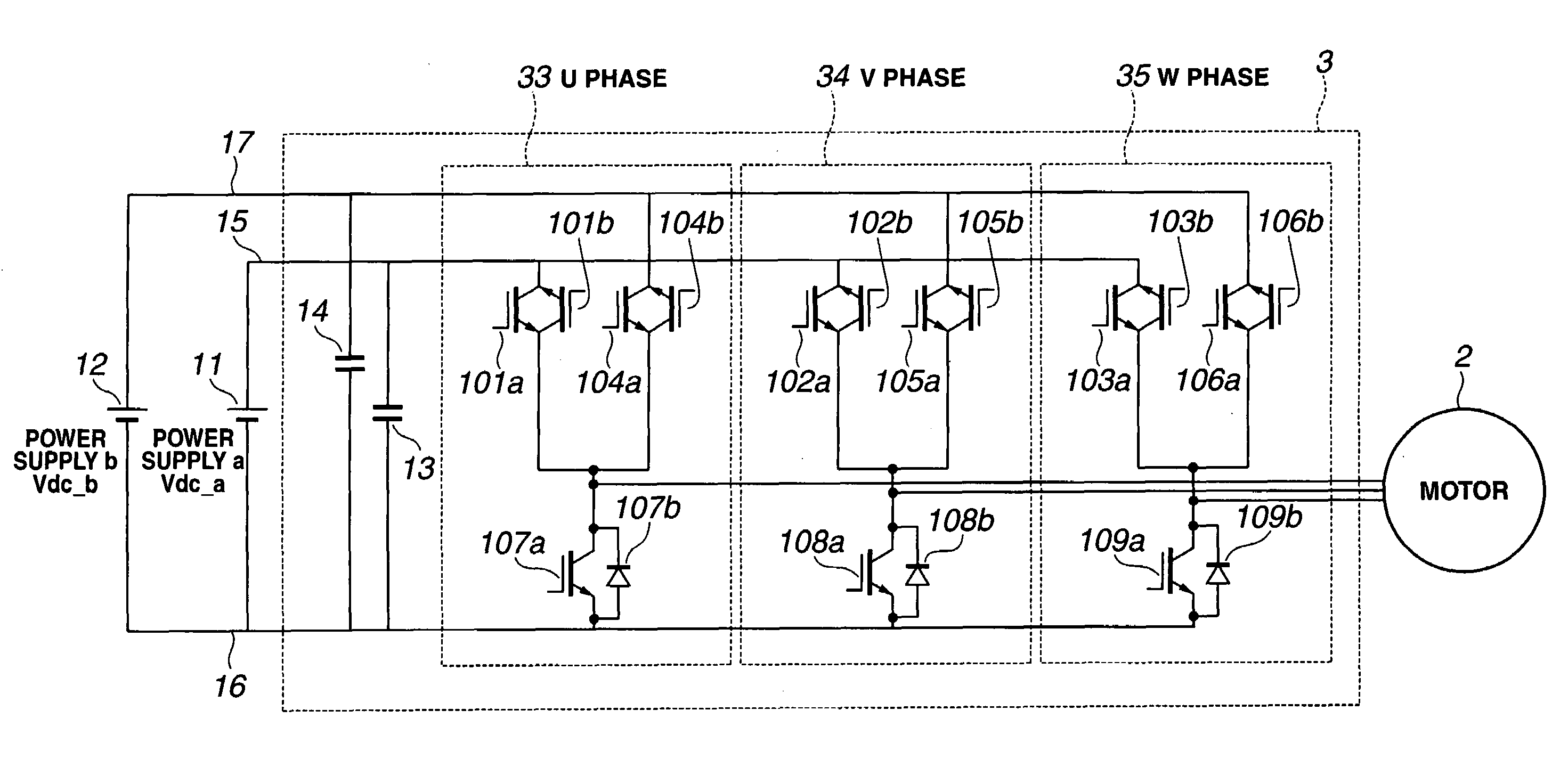
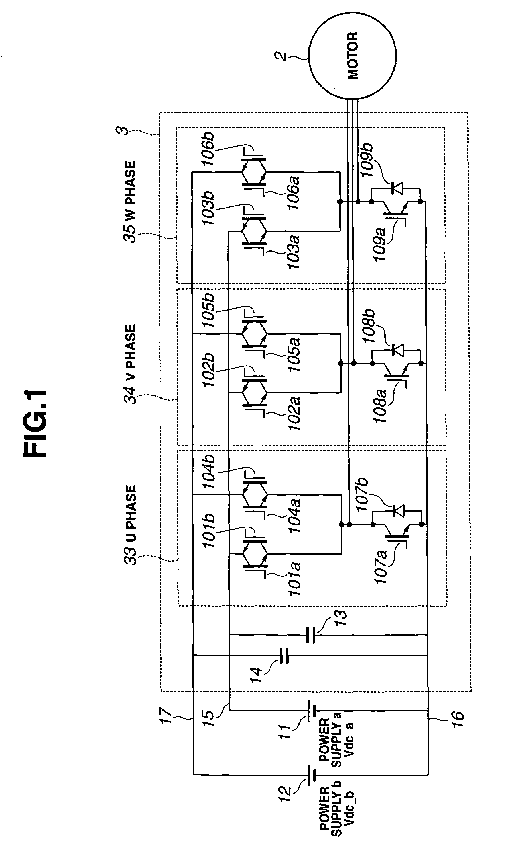
[0042]FIG. 1 shows a schematic circuit diagram of a power converter of an electric power conversion apparatus in accordance with a first embodiment of the present invention. The power converter is adapted to be electrically connected to a plurality of voltage sources and to a three-phase synchronous electric motor. In the circuit diagram of FIG. 1, the negative pole of a DC voltage source a 11 and the negative pole of a DC voltage source b 12 are both electrically connected to a common negative bus 16. A power converter 3 includes a U-phase section 33, a V-phase section 34 and a W-phase section 35, each of which includes a contact adapted to be electrically connected to a respective one of the contacts of a three-phase synchronous electric motor 2. Between common negative bus 16 and the contact of U-phase section 33, V-phase section 34 and W-phase section 35 are disposed a combination of a semiconductor switch 107a and a diode 107b, a combination of a semiconductor switch 108a and a...


PUM


Abstract

An electric power conversion apparatus includes a power converter connected to at least a first DC voltage source, a second DC voltage source and an AC electric motor. A control unit controls the power converter to generate a first PWM pulse train for supplying a first output voltage pulse train from the first DC voltage source to the AC electric motor and a second PWM pulse train for supplying a second output voltage pulse train from the second DC voltage source to the load in such a manner to form a pulse continuous in time in a final output voltage at least from each pulse of the first output voltage pulse train and a subsequent pulse of the second output voltage pulse train. A current path is provided constantly from the AC electric motor to at least one of the DC voltage sources.

Description

BACKGROUND OF THE INVENTION[0001]The present invention relates generally to electric power conversion apparatuses and methods, and more particularly to electric power conversion apparatuses and methods adapted to be electrically connected to a plurality of power supplies.[0002]Japanese Patent Application Publication No. 2002-118981 (JP2002-118981) shows an electric power conversion system which employs a fuel cell as a main power supply and a battery as a sub power supply to drive an electric motor. While the fuel cell is connected electrically and directly to the motor, the battery is electrically connected to the motor via a DCDC (Direct Current to Direct Current) converter. The output voltage of the DCDC converter is controlled in order to improve the output efficiency of the power supplies.SUMMARY OF THE INVENTION[0003]In the electric power conversion system of JP2002-118981, the provision of the DCDC converter causes an increase in the size of the whole system including the pow...

Claims


Application Information

Patent Timeline
Patent Type & Authority Patents(United States)
IPC IPC(8): H02M7/5387
CPCB60L11/1881H02M7/53875H02M7/483Y02T90/34B60L58/30Y02T90/40
Inventor YOSHIMOTO, KANTARO
Owner NISSAN MOTOR CO LTD
Why Eureka
Try Eureka