
Core voltage discharge driver

a core voltage and driver technology, applied in the direction of power consumption reduction, digital storage, instruments, etc., can solve the problems of unstable operation of the driver, difficult to supply a sufficient amount of current at a time, data stored in the unit cell can be damaged, etc., to prevent the operation of the core voltage discharging operation

Inactive Publication Date: 2009-09-08
SK HYNIX INC
View PDF10 Cites 4 Cited by
  • Summary
  • Abstract
  • Description
  • Claims
  • Application Information

AI Technical Summary

Benefits of technology

[0030]Embodiments of the present invention are directed to providing a core voltage discharge driver for preventing a core voltage discharging operation from interrupting the core voltage generating operation.

Problems solved by technology

That is, due to generation of a leakage current, data stored in the unit cell can be damaged.
However, due to drop of an operation voltage according to the tendency of the low power consumption, it is difficult to supply a sufficient amount of the current at a time.
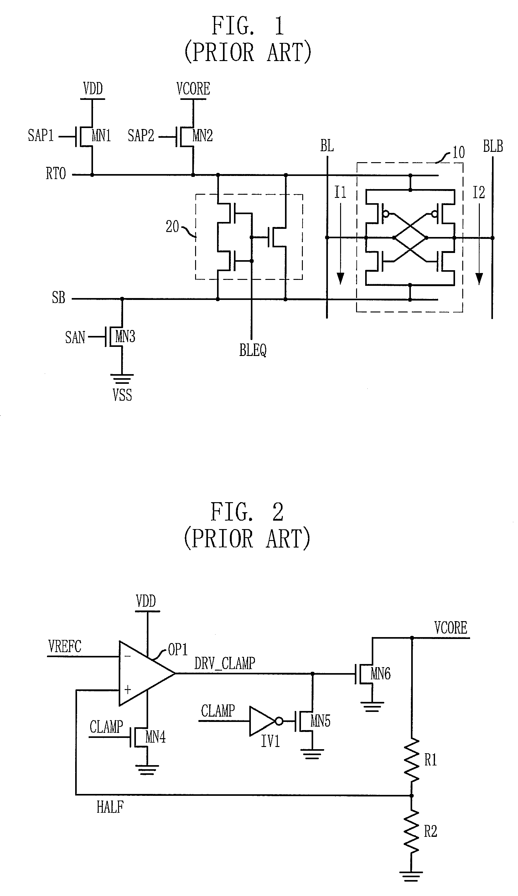
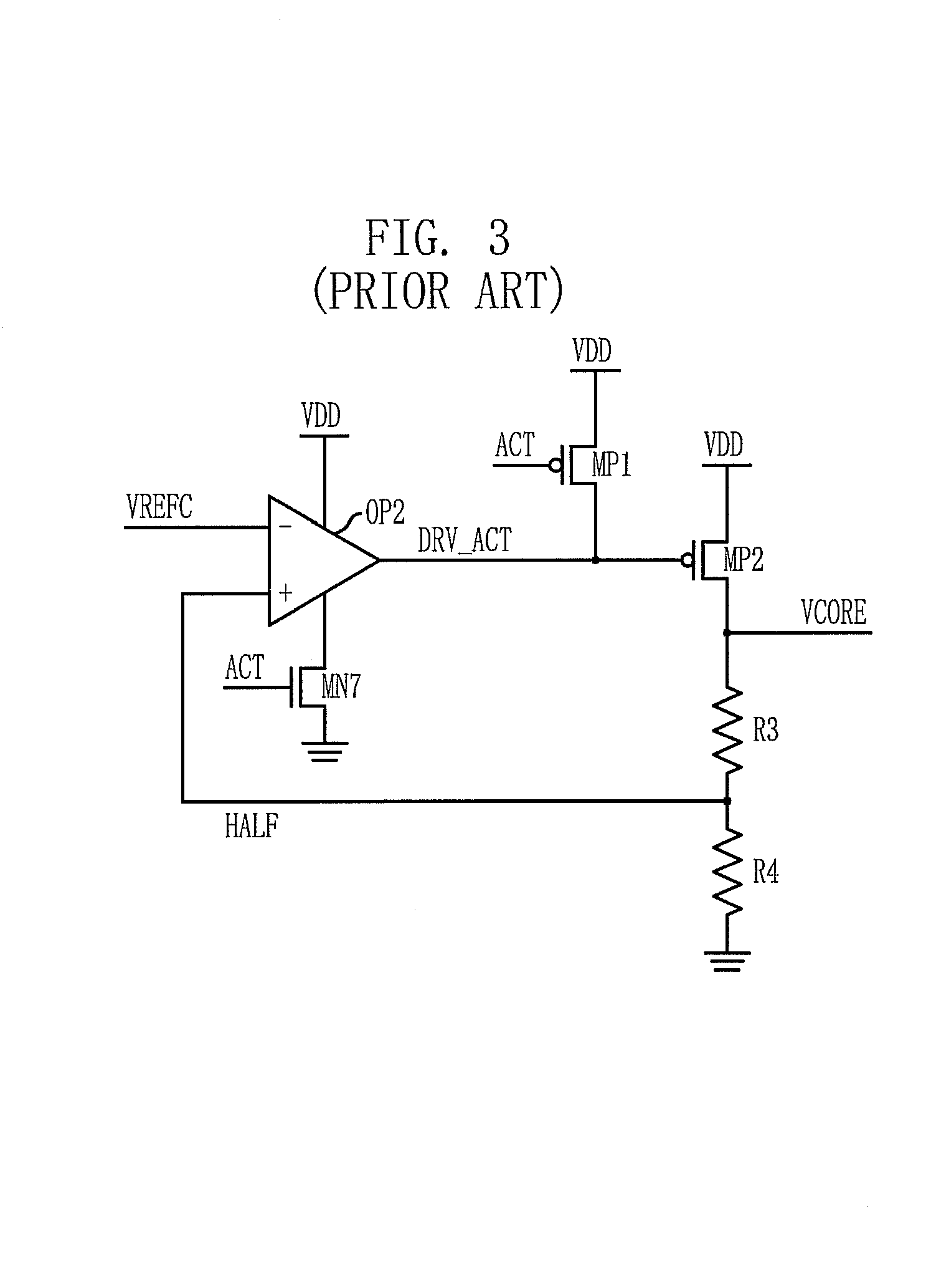
Since the size of the PMOS transistor MP2 serving as the driving unit is larger than the size of the NMOS transistor MN6, the core voltage VCORE increases, but unnecessary current is consumed in the period A. In addition, due to decrease of the level of the core voltage VCORE, operation of the driver may be unstable.

Method used


Image

  • Core voltage discharge driver
  • Core voltage discharge driver
  • Core voltage discharge driver

Examples


Embodiment Construction

[0039]Hereinafter, a core voltage discharge driver in accordance with the present invention will be described in detail with reference to the accompanying drawings.

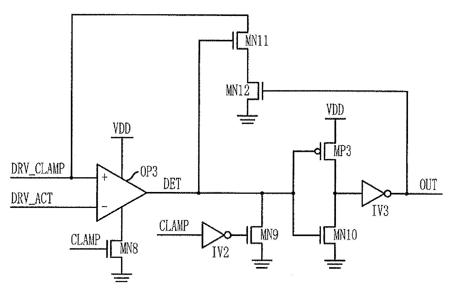
[0040]FIG. 5 is a circuit diagram of a core voltage discharge driver in accordance with an embodiment of the present invention.

[0041]The core voltage discharge driver is connected to an output terminal of the conventional core voltage discharge driver of FIG. 2 and an output terminal of the conventional core voltage generator of FIG. 3. By using feedback in comparing an output signal DRV_CLAMP of the op-amp OP1 in the conventional core voltage discharge driver and an output signal DRV_ACT of the op-amp OP2 in the conventional core voltage generator, the core voltage discharge driver controls a discharge operation of the core voltage VCORE in order that the discharge operation does not interrupt a generation operation of the core voltage VCORE.

[0042]An op-amp OP3 of the core voltage discharge driver receives the output sig...


PUM


Abstract

A core voltage discharge driver prevents a core voltage discharging operation from interrupting the core voltage generating operation. The core voltage discharge driver includes a comparing unit configured to compare a core voltage generating control signal for controlling generation of a core voltage with a core voltage discharging control signal for controlling discharge of the core voltage, and an adjusting unit configured to adjust the core voltage discharging control signal based on a comparison result of the comparing unit.

Description

CROSS-REFERENCE TO RELATED APPLICATIONS[0001]The present invention claims priority to Korean patent application number 10-2007-0092521, filed on Sep. 12, 2007, which is incorporated by reference in its entirety.BACKGROUND OF THE INVENTION[0002]The present invention relates to a core voltage discharge driver.[0003]In a memory device such as a dynamic random access memory (DRAM) device, a unit cell generally includes one transistor and one capacitor in which electric charges are stored as data. Since the capacitor formed on a semiconductor substrate is not fully electrically insulated from other components, the stored electric charges are discharged. That is, due to generation of a leakage current, data stored in the unit cell can be damaged. Accordingly, the memory device performs refresh operation periodically in order to maintain charges stored in the capacitor.[0004]Changing internal addresses by itself, the memory device having a refresh mode performs the refresh operation in res...

Claims


Application Information

Patent Timeline
Patent Type & Authority Patents(United States)
IPC IPC(8): G11C7/00G11C5/14
CPCG11C5/147G11C11/4091G11C11/4074G11C7/06H03K19/0016H03K19/0185
Inventor CHOI, JUN-GI
Owner SK HYNIX INC
Learn More