Single-mode optical fiber

a single-mode, optical fiber technology, applied in the field of line fiber, can solve the problems of fiber being subject to harsh installation constraints, fiber being commercially incompatible with certain transmission systems, and slightly different profiles, and achieve the effect of reducing bending losses and reducing leakage modes

Active Publication Date: 2009-09-08
DRAKA COMTEQ BV
View PDF123 Cites 233 Cited by
  • Summary
  • Abstract
  • Description
  • Claims
  • Application Information

AI Technical Summary

Benefits of technology

[0030]With such a structure, it is possible to effectively reduce the bending losses at constant MAC while strongly minimizing the leakage modes of a higher order. Thus, unlike the fibers from the prior art having a step-index structure with a depressed section, the fiber of the invention has a cable cut-off wavelength which remains less than 1260 mm. The fiber of the invention thus complies with the G.652 standard.

Problems solved by technology

Constraints in manufacturing the fiber, however, may lead to a slightly different profile.
Now, a reduction in MAC, by reducing the mode field diameter and / or by increasing the effective cut-off wavelength, may lead away from the G.652 standard and make the fiber commercially incompatible with certain transmission systems.
Moreover, within the scope of FTTH or FTTC applications, the fiber risks being subject to harsher installation constraints than in applications at longer distances (i.e., the presence of accidental bendings related to the installation and to the environment).
Nevertheless it is understood that this reduction in bending losses should not be achieved to the detriment of a loss of the single mode character of the signal.
This would strongly deteriorate the signal or detrimentally introduce significant junction optical losses.
Nevertheless, such fibers have significant coupling losses and are not adapted to the FTTH applications described previously.
The cost for manufacturing such a fiber and the presently high attenuation levels (>0.25 dB / km), however, make commercial use in FTTH or FTTC systems impractical.
Further, with these fibers, it is simply not possible to achieve the optical characteristics recommended by the G.652 standard, notably in terms of chromatic dispersion.
Moreover, the fiber will be subject to significant bending stresses related to the environment of its installation.

Method used


Image

  • Single-mode optical fiber
  • Single-mode optical fiber
  • Single-mode optical fiber

Examples


Embodiment Construction

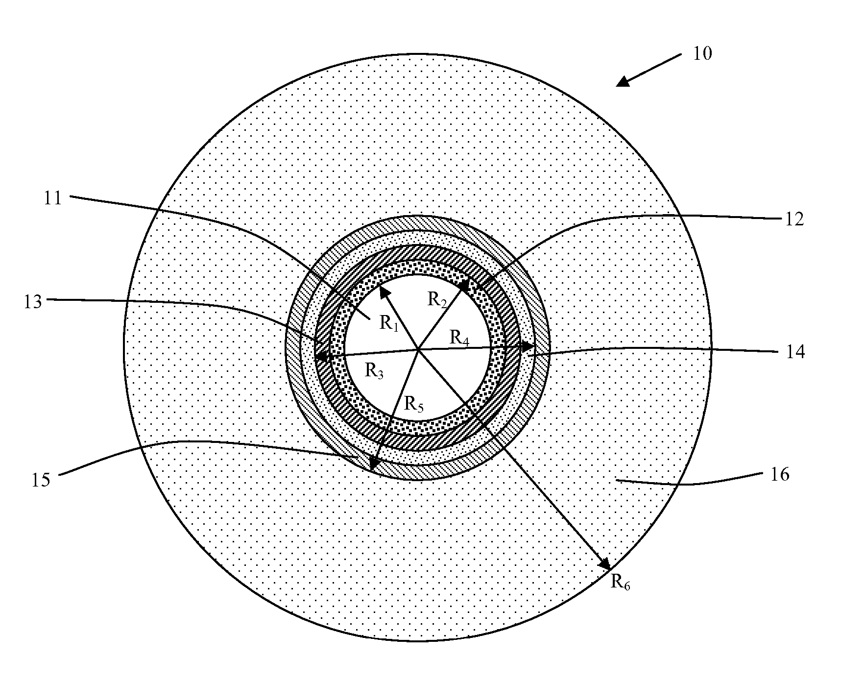
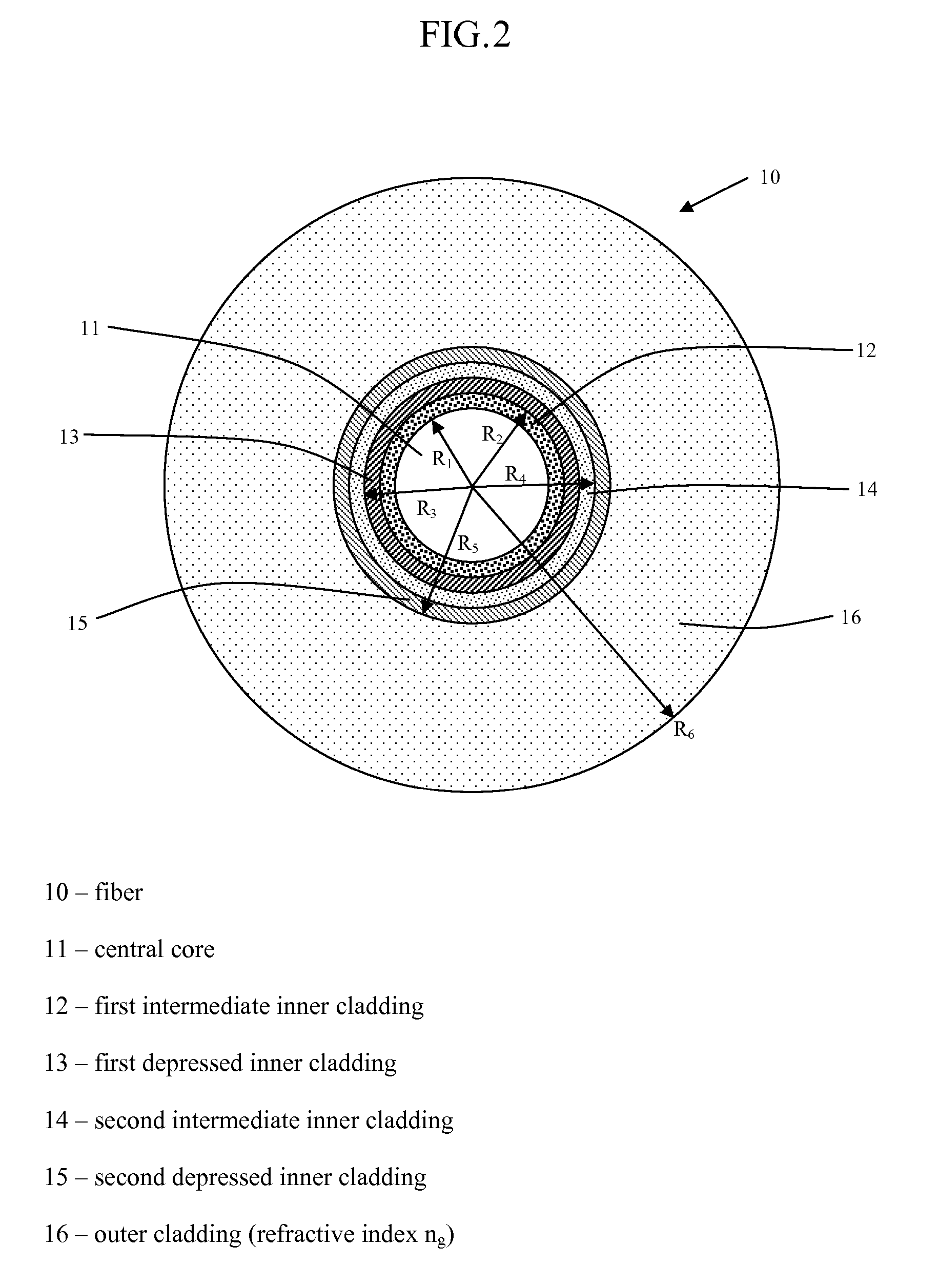
[0041]With reference to FIG. 2, the fiber 10 of the invention has a central core 11, a first intermediate inner cladding 12, and a first depressed inner cladding 13. The fiber also has a second intermediate inner cladding 14 and a second depressed inner cladding 15. By depressed inner cladding, it is meant that a radial portion of the fiber 10 has a refractive index less than the index of the outer optical cladding 16. The first depressed inner cladding 13 has an index difference with the outer optical cladding 16 that is typically less than −5×10⁻³ but that may reach −15×10−3. The second depressed inner cladding 15 has a smaller index difference with the outer cladding 16 than with the first depressed inner cladding 13; this index difference is typically between −0.3×10⁻³ and −3×10⁻³.

[0042]As will be appreciated by those having ordinary skill in the art, FIG. 2 is a schematic representation of an exemplary fiber. FIG. 2 is intended to depict the relative positions of the central co...


PUM


Abstract

Disclosed is an optical transmission fiber having reduced bending and microbending losses that is commercially usable in FTTH or FTTC transmission systems.

Description

CROSS-REFERENCE TO PRIORITY APPLICATIONS[0001]This application hereby claims the benefit of pending French Application No. 06 / 03128 (filed Apr. 10, 2006 at the French Patent Office), which is hereby incorporated by reference in its entirety.FIELD OF THE INVENTION[0002]The present invention relates to the field of transmissions through optical fiber and more specifically to a line fiber having reduced bending and microbending losses.BACKGROUND OF THE INVENTION[0003]For optical fibers, the index profile is generally described as the graphical appearance of the function that associates the refractive index with the radius of the fiber. Conventionally, the distance (r) to the center of the fiber is represented on the abscissa and the difference between the refractive index and the refractive index of the fiber cladding is represented on the ordinate. The index profile is thereby termed as a “step,”“trapezium,” or “triangle” for graphs that have the shapes of a step, a trapezium, or a tr...

Claims


Application Information

Patent Timeline
Patent Type & Authority Patents(United States)
IPC IPC(8): G02B6/36
CPCG02B6/03688G02B6/02266G02B6/028G02B6/036
Inventor DE MONTMORILLON, LOUIS-ANNEMOLIN, DENISMATTHIJSSE, PIETERGOOIJER, FRANSPETITFRERE, EMMANUELLUMINEAU, YVESACHTEN, FRANCISCUS JOHANNESBIGOT-ASTRUC, MARIANNESILLARD, PIERRENOUCHI, PASCALE
Owner DRAKA COMTEQ BV
Why Eureka
Try Eureka