
Camera interface and method using DMA unit to flip or rotate a digital image

a digital image and camera technology, applied in the field of digital camera systems, can solve problems such as difficult to change a ccd image sensor to correct such an upset image, image upset may occur, and may require correction

Active Publication Date: 2009-09-08
SAMSUNG ELECTRONICS CO LTD
View PDF17 Cites 16 Cited by
  • Summary
  • Abstract
  • Description
  • Claims
  • Application Information

AI Technical Summary

Benefits of technology

Enables efficient image correction with reduced memory requirements and minimized delays, maintaining high-bandwidth and low-power performance in mobile devices by directly accessing and transforming image data within the camera module.

Problems solved by technology

In employing the CCD image sensor in a mobile phone, an image upset phenomenon may occur.
Such an image upset (e.g., a flip or a rotation) is caused by lenses and / or mirrors and positional variation of the camera module of the mobile phone.
Therefore, the image upset may require correction by digitally reversing the mirrored image.
But, it is difficult to change a CCD image sensor to correct such an upset image because charges (or image signals) therein are detected in the pattern of shift registers directly coupled with the photodiode array and thereby the order of horizontal lines of an output image is fixed.
Using the high-capacity frame buffer in the camera module may cause unnecessary requirements for high-capacity memory and may generate delays in the availability of image data du to the frame buffering processes.
Using the external memory in the CCD image sensor may cause frequent unnecessary memory accessing operations, which can hinder he implementation of high-bandwidth, low-power, and small-size mobile phones.

Method used


Image

  • Camera interface and method using DMA unit to flip or rotate a digital image
  • Camera interface and method using DMA unit to flip or rotate a digital image
  • Camera interface and method using DMA unit to flip or rotate a digital image

Examples


Embodiment Construction

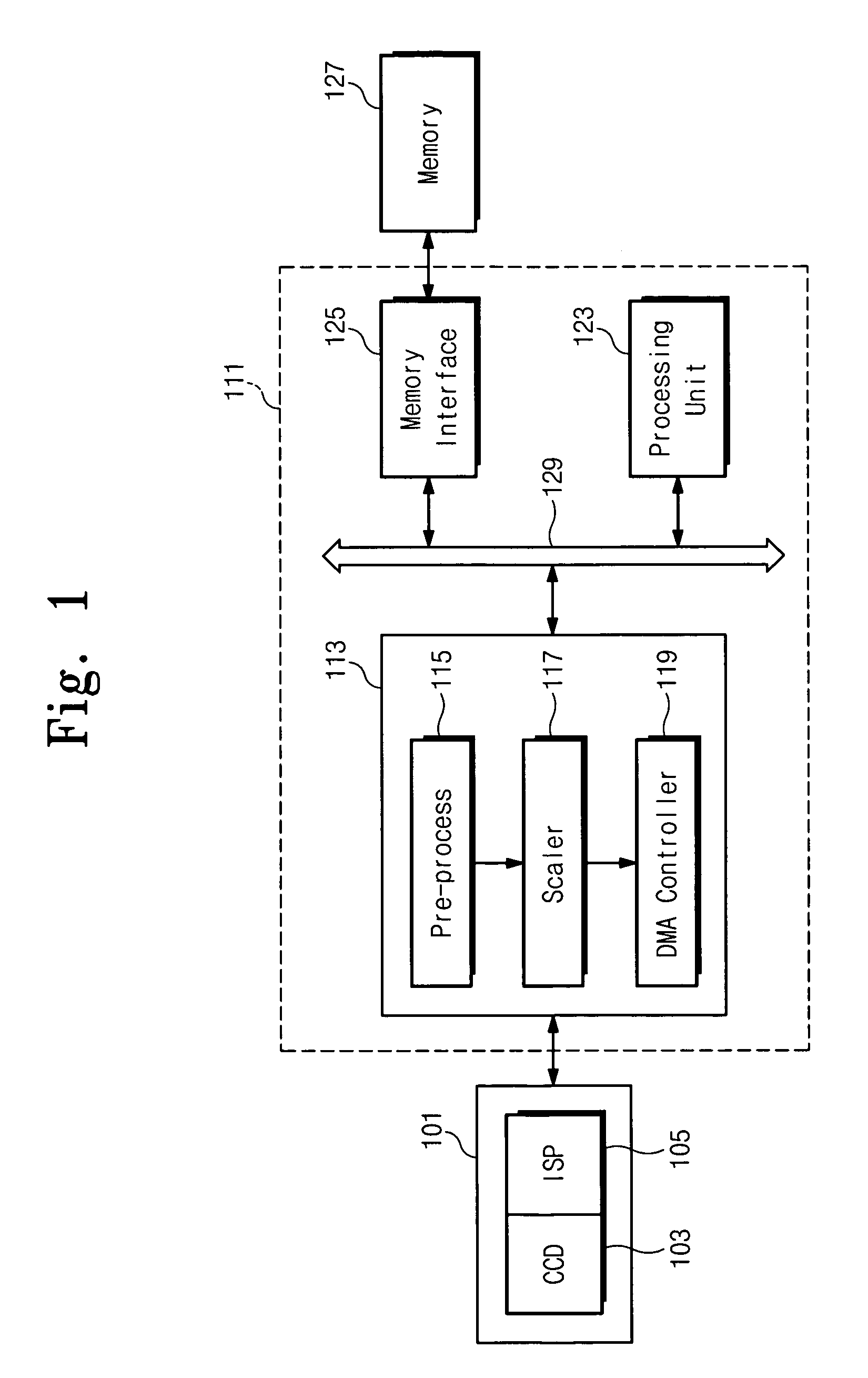
[0046]FIG. 1 is a block diagram illustrating a camera module 101 and an application processor 111 in a mobile phone in accordance with an embodiment of the present invention. Referring to FIG. 1, the camera module 101 comprise an image sensor 103 and an image signal processor (ISP) 105. The image sensor 103 may be comprised of a CCD image sensor or a CMOS image sensor. The application processor 111 includes a camera interface 113, a processing unit 123, a memory interface 125, and a system bus 129 for operatively interconnecting them. The system bus 129 is for example an advanced high performance (AHB) bus, being connected to an external frame memory 127 that is a synchronous DRAM as an example. The camera interface 113 comprise a pre-processor 115, a color scaler 117, and a DMA (controller) unit 119 for performing the image transforming functions.

[0047]After converting an optical (real) image by receiving light originating from a subject into an electrical signal by the image senso...


PUM


Abstract

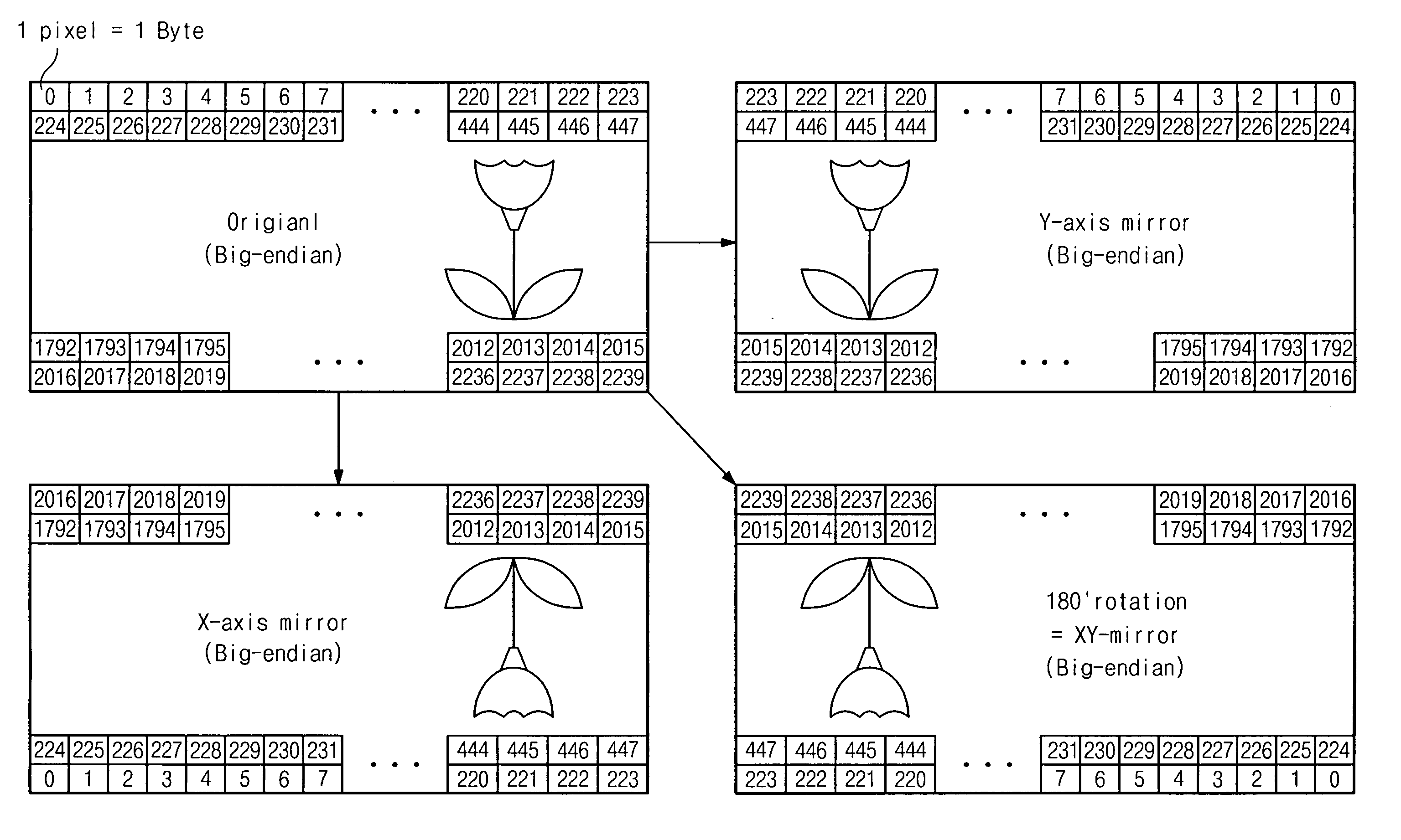
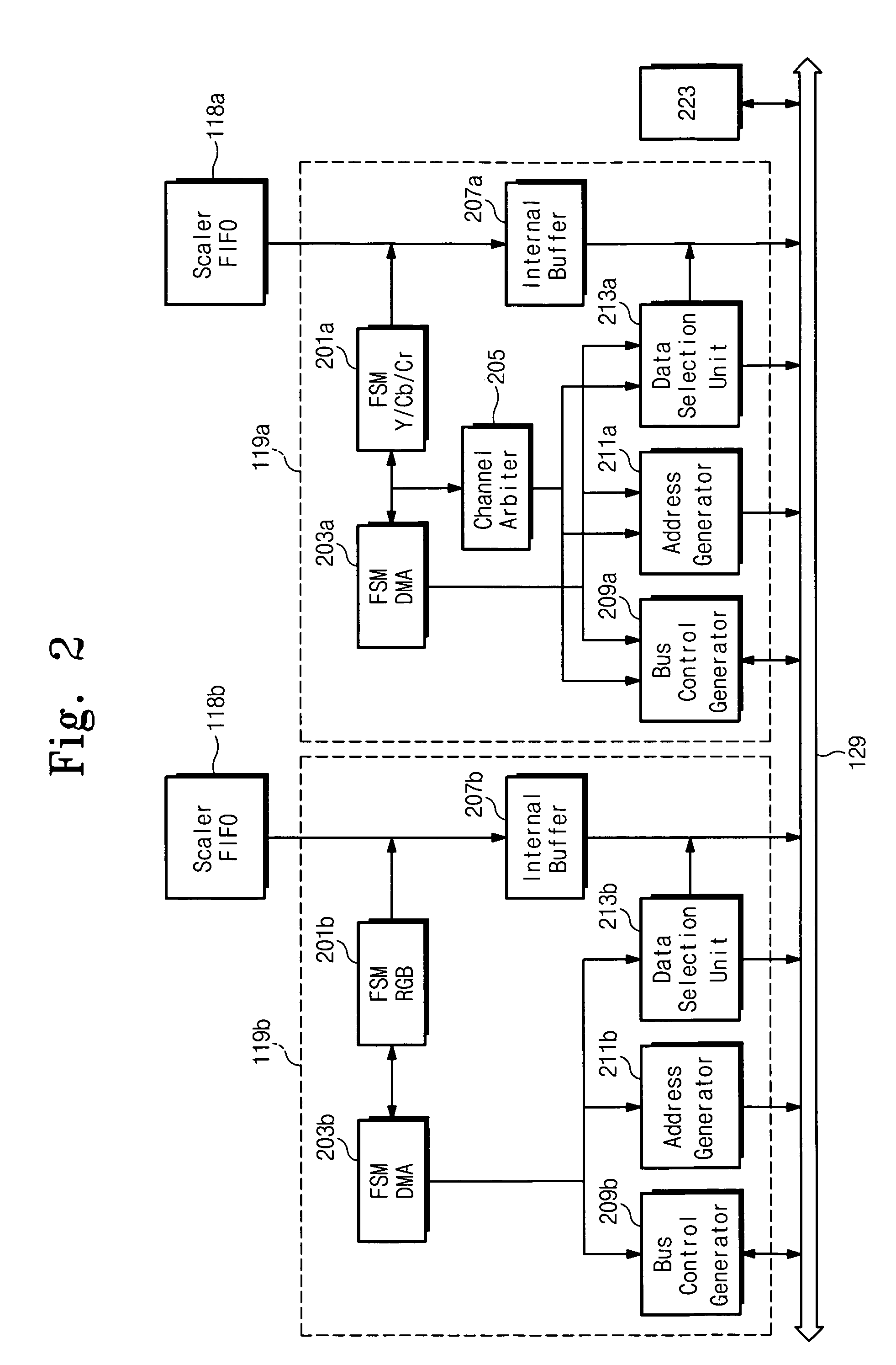
A camera interface employing a direct memory access (DMA) unit to digitally perform an image transformation such as “flipping” and “rotating” an image (e.g., to correct for X-axis, Y-axis, or XY-axes mirroring). The image transforming DMA unit includes an address generator and a data selector. The address generator appropriately modifies a frame start address, a burst transfer address, a line start address, of an image frame, based on the X, Y, or XY mirrored image mode. The data selector changes the sequences of words and of pixels in a word based upon the mirrored image mode. The data selector includes a plurality of pixel-sequence modifying multiplexers each for selecting between a word having an original pixel sequence stored in the buffer memory and a word having the reverse pixel sequence; and a word-sequence modifying multiplexer outputting the selected words in the original word sequence or in the reverse word sequence in response to outputs of a counter that increments or decrements based upon the mirrored image mode.

Description

CROSS-REFERENCE TO RELATED APPLICATIONS[0001]This application claims priority, under 35 U.S.C. § 119, of Korean Patent Application 2004-01618 filed on Jan. 9, 2004, the entire contents of which are hereby incorporated by reference.FIELD OF THE INVENTION[0002]The present invention relates to digital camera systems, and more particularly to a camera interface for implementing an image transform to correct for X-axis, Y-axis, or XY-axes mirroring, using a direct memory access (DMA) unit.DISCUSSION OF RELATED ART[0003]Rapid development in the mobile communication industry has enabled consumers to enjoy convenience in sharing information, particularly images, using cellphones and other portable (or mobile) terminals. Since the early days of using the mobile phones only for voice (audio) calls and message transmission, their function has been recently extended even to downloading MP3 music files through of the wireless mobile internet network. Now, in response to consumer demand for imagi...

Claims


Application Information

Patent Timeline
Patent Type & Authority Patents(United States)
IPC IPC(8): G06F13/28G06F7/00G06K9/32G06K9/36G06T1/60G06T3/00G11C7/00H04N1/387H04N7/14H04N23/90
CPCH04N1/3247H04N5/232H04N5/23293H04N2201/0084H04N2101/00H04N23/63E06B3/84E06B2003/7051E05Y2800/406Y10S707/99942
Inventor CHO, JIN-HYUNKANG, JUNG-SUNLEE, JIN-AEONPARK, YOUNG-HA
Owner SAMSUNG ELECTRONICS CO LTD
Learn More