Adaptive defrost control circuit with relay power saving feature

a control circuit and relay technology, applied in the direction of defrosting, heating apparatus, domestic cooling apparatus, etc., can solve the problem of primarily reactive power dispersion across the circuit, and achieve the effect of reducing the amount of real power consumed, and reducing the amount of heat generated

Inactive Publication Date: 2009-09-15
ROBERTSHAW CONTROLS CO
View PDF3 Cites 0 Cited by
  • Summary
  • Abstract
  • Description
  • Claims
  • Application Information

AI Technical Summary

Benefits of technology

[0008]The present invention provides a new and improved defrost heater control circuit that overcomes one or more problems existing in the art. More particularly, the present invention provides a new and improved defrost control circuit that reduces the heat generated during a standby mode of operation when the defrost heater is not operated. Still more particularly, the present invention provides a new and improved defrost heater control circuit that reduces the amount of real power consumed during a standby mode of operation to therefore reduce the amount of heat generated during such mode.
[0009]In one embodiment of the present invention the defrost heater control circuit includes a relay to switch power to the defrost heater, and a relay drive circuit. In this embodiment the relay drive circuit utilizes a twenty four volt supply to energize the relay, which connects the heater power supply to the heater element to provide the defrost mode of operation. However, when the relay is turned off, the circuit of the present invention saves real power by effectively shorting out the relay power supply.
[0010]In a preferred embodiment of the present invention, the defrost control circuit provides a capacitor in series with the line AC voltage to act as a dropping impedance. While this would apparently increase the current to the drive circuit when the relay is off, due to the increased voltage across the capacitor, the result is that the power dissipated across the circuit is primarily reactive, i.e., not real power that would be turned into heat. As a result the amount of heat generated by the circuit when the relay for the defrost heater is held off is substantially reduced.

Problems solved by technology

While this would apparently increase the current to the drive circuit when the relay is off, due to the increased voltage across the capacitor, the result is that the power dissipated across the circuit is primarily reactive, i.e., not real power that would be turned into heat.

Method used


Image

  • Adaptive defrost control circuit with relay power saving feature
  • Adaptive defrost control circuit with relay power saving feature
  • Adaptive defrost control circuit with relay power saving feature

Examples


Embodiment Construction

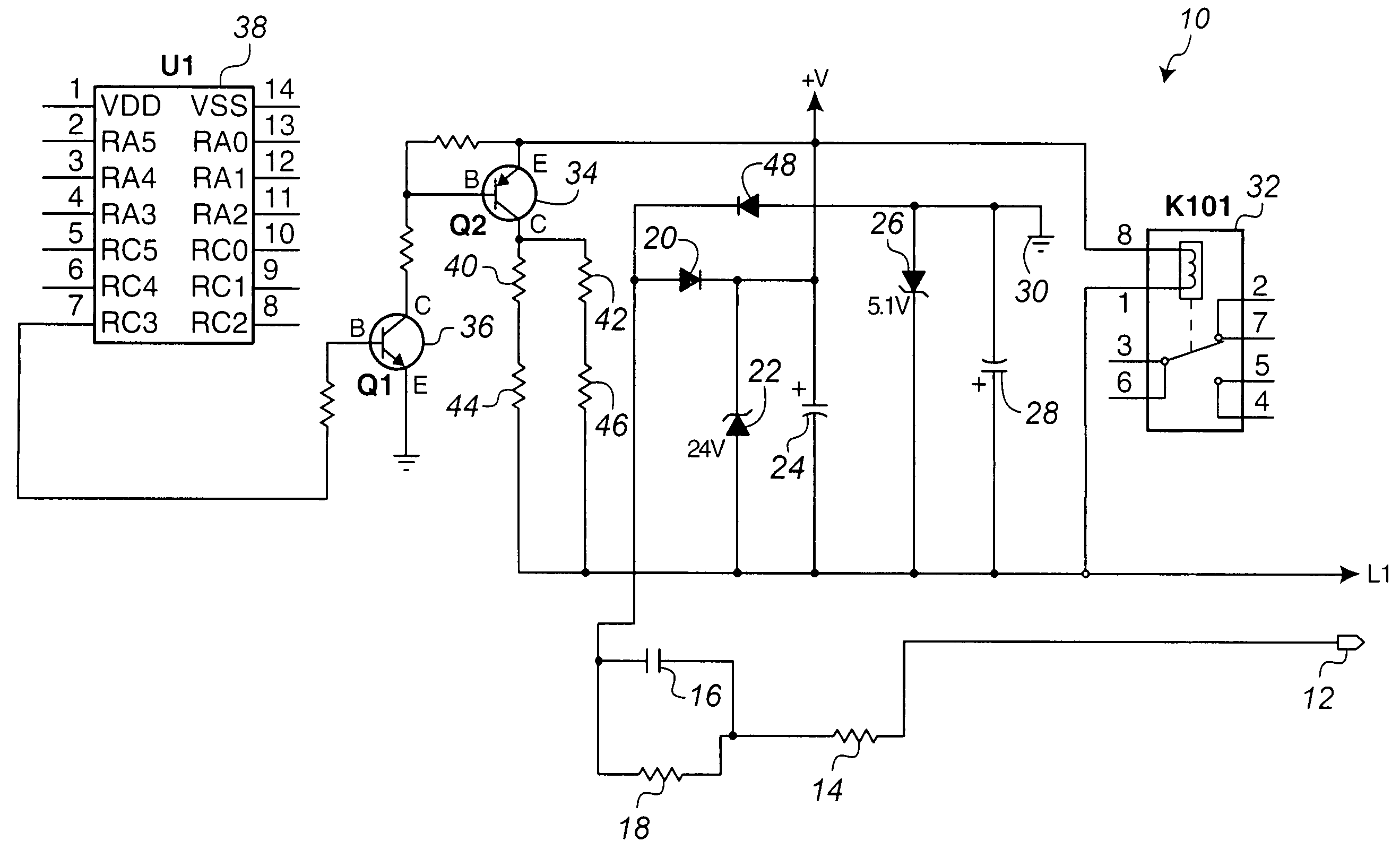
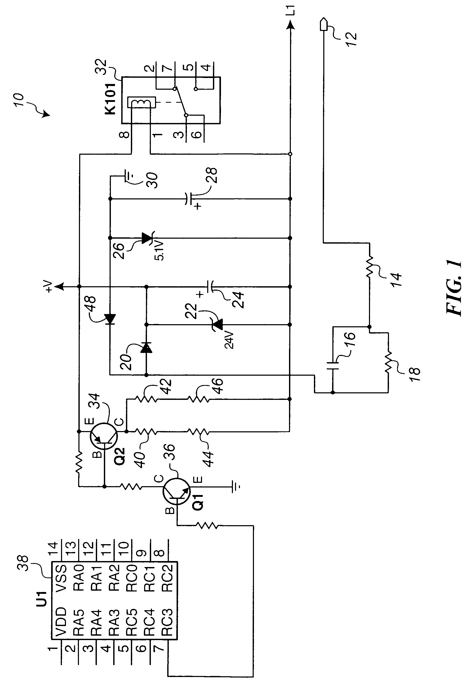
[0019]FIG. 1 illustrates one embodiment of a defrost heater relay drive circuit 10 constructed in accordance with the teachings of the present invention. This circuit 10 controls the on or off state of the defrost heater (not shown) in, for example, a consumer or commercial refrigerator and / or freezer. An advantage provided by the circuit of FIG. 1 is that the real power dissipation, and therefore heat generation, during periods when the defrost heater is de-energized is greatly reduced compared with other defrost heater relay drive circuits. Since approximately twice the amount of energy is needed to remove a unit of heat from the refrigeration compartment, any reduction in heat generated during periods when the defrost heater is not to be energized greatly enhances the efficiency of the system and reduces the overall cost of operation and lifetime costs of ownership of the appliance.

[0020]As illustrated in FIG. 1, the power for the circuit is taken from the line voltage via power ...


PUM


Abstract

A defrost heater relay control circuit having reduced power consumption during a de-energized mode of operation is provided. The relay drive circuit utilizes a series connected capacitor to introduce a phase shift in the AC current waveform such that the amount of real power dissipated in the circuit during periods when the defrost heater control relay is de-energized is greatly reduced. This effectively shorts out the relay drive voltage without generating heat due to real power dissipation through the switched circuitry that disables the relay.

Description

FIELD OF THE INVENTION[0001]The present invention relates generally to defrost control circuitry for consumer and commercial refrigeration appliances, and more particularly to power reduction circuitry for use with such defrost control systems.BACKGROUND OF THE INVENTION[0002]Recognizing that icing of the evaporator heat exchanger in a consumer or commercial refrigeration unit, such as a refrigerator or freezer, many modern appliances provide fixed or adaptive defrost control. Such a defrost control provides heating of the evaporator heat exchanger so as to melt any accumulated frost or ice that may have formed thereon during the refrigeration cooling cycle. Many different methods of controlling the defrost cycle are known in the art, including electromechanical timers and microprocessor control.[0003]Typically, such defrosting circuitry employs a heater positioned in proximity to the evaporator heat exchanger within the freezer compartment of the refrigerator or freezer. At control...

Claims


Application Information

Patent Timeline
Patent Type & Authority Patents(United States)
IPC IPC(8): F25D21/06F25D21/00
CPCF25D21/006F25D21/08
Inventor ESTES, BAYJENSKI, LEONARD W.
Owner ROBERTSHAW CONTROLS CO
Why Eureka
Try Eureka