Power impact tool

a tool and power technology, applied in the field of power impact tools, can solve the problems of unnecessary vibration and loss of striking energy of the tool bit, and achieve the effect of improving the vibration reduction performan

Active Publication Date: 2009-09-15
MAKITA CORP
View PDF8 Cites 31 Cited by
  • Summary
  • Abstract
  • Description
  • Claims
  • Application Information

AI Technical Summary

Benefits of technology

[0006]Accordingly, it is an object of the invention to provide a technique for further improving the vibration reducing performance in a power impact tool that linearly drives a tool bit by using a swinging mechanism.

Problems solved by technology

As a result, when the tool driving mechanism and the counter weight are driven by the swinging ring, unnecessary vibration is caused by a couple around the horizontal axis that intersects with the axis of the rotating shaft.
Further, because the counter weight linearly moves by the swinging movement of the swinging ring, loss of a striking energy of the tool bit may be caused by resistance of the sliding area.

Method used


Image

  • Power impact tool
  • Power impact tool
  • Power impact tool

Examples


first representative embodiment

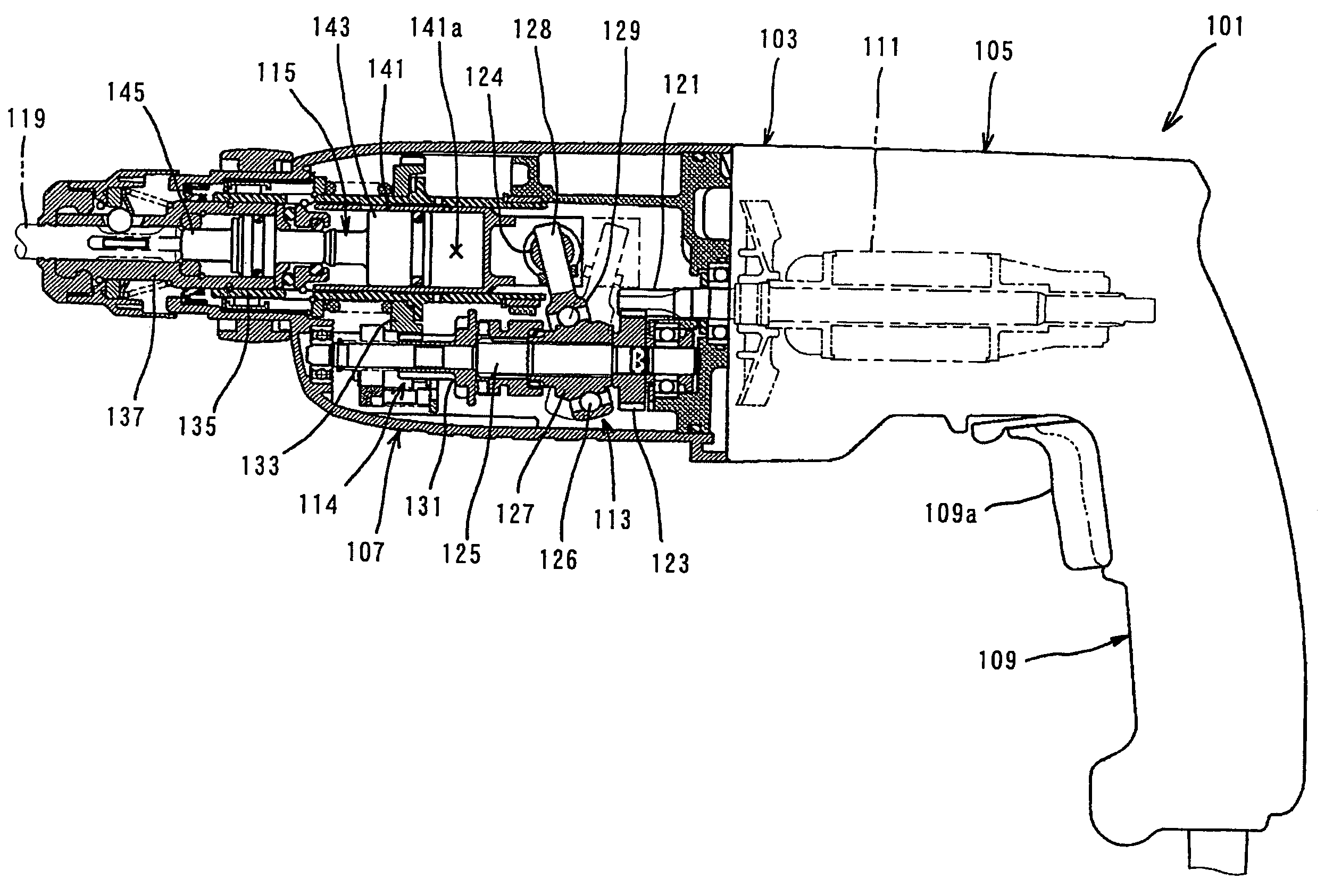
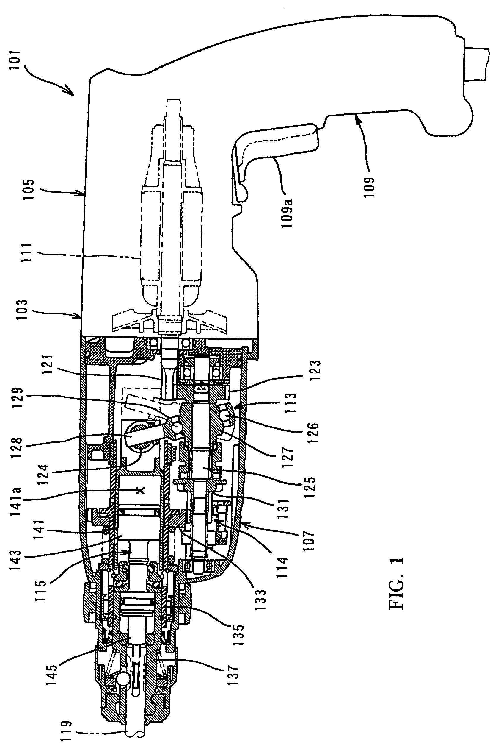
[0038]First representative embodiment of the present invention will now be described with reference to FIGS. 1 to 4. As shown in FIG. 1, an electric hammer drill 101 as a representative embodiment of the power impact tool according to the present invention comprises a body 103 and a hammer bit 119 detachably coupled to the tip end region of the body 103 via a tool holder 137. The hammer bit 119 is a feature that corresponds to the “tool bit” according to the present invention.

[0039]The body 103 includes a motor housing 105, a gear housing 107 and a handgrip 109. The motor housing 105 houses a driving motor 111. The gear housing 107 houses a motion converting mechanism 113, a power transmitting mechanism 114 and a striking mechanism 115. The driving motor 111 is a feature that corresponds to the “motor” according to the present invention. The rotating output of the driving motor 111 is appropriately converted into linear motion via the motion converting mechanism 113 and transmitted ...

second representative embodiment

[0054]Now, the vibration reducing mechanism 151 according to a second representative embodiment of the present invention is explained with reference to FIGS. 5 to 7. FIG. 5 shows an internal mechanism disposed within the gear housing 107. FIG. 6 is an external view of the vibration reducing mechanism part, and FIG. 7 is a sectional view of the vibration reducing mechanism part. Like in the fist embodiment, the vibration reducing mechanism 151 of the second embodiment also includes a counter weight 163 which is driven by the swinging ring 129. The pivot point of the counter weight 163 is located at a higher position than in the first embodiment. Except this point, the second embodiment has the same construction as the first embodiment. Components or elements in the second embodiment which are substantially identical to those in the first embodiment are given like numerals as in the first embodiment and will not be described. The counter weight 163 is a feature that corresponds to the...

third representative embodiment

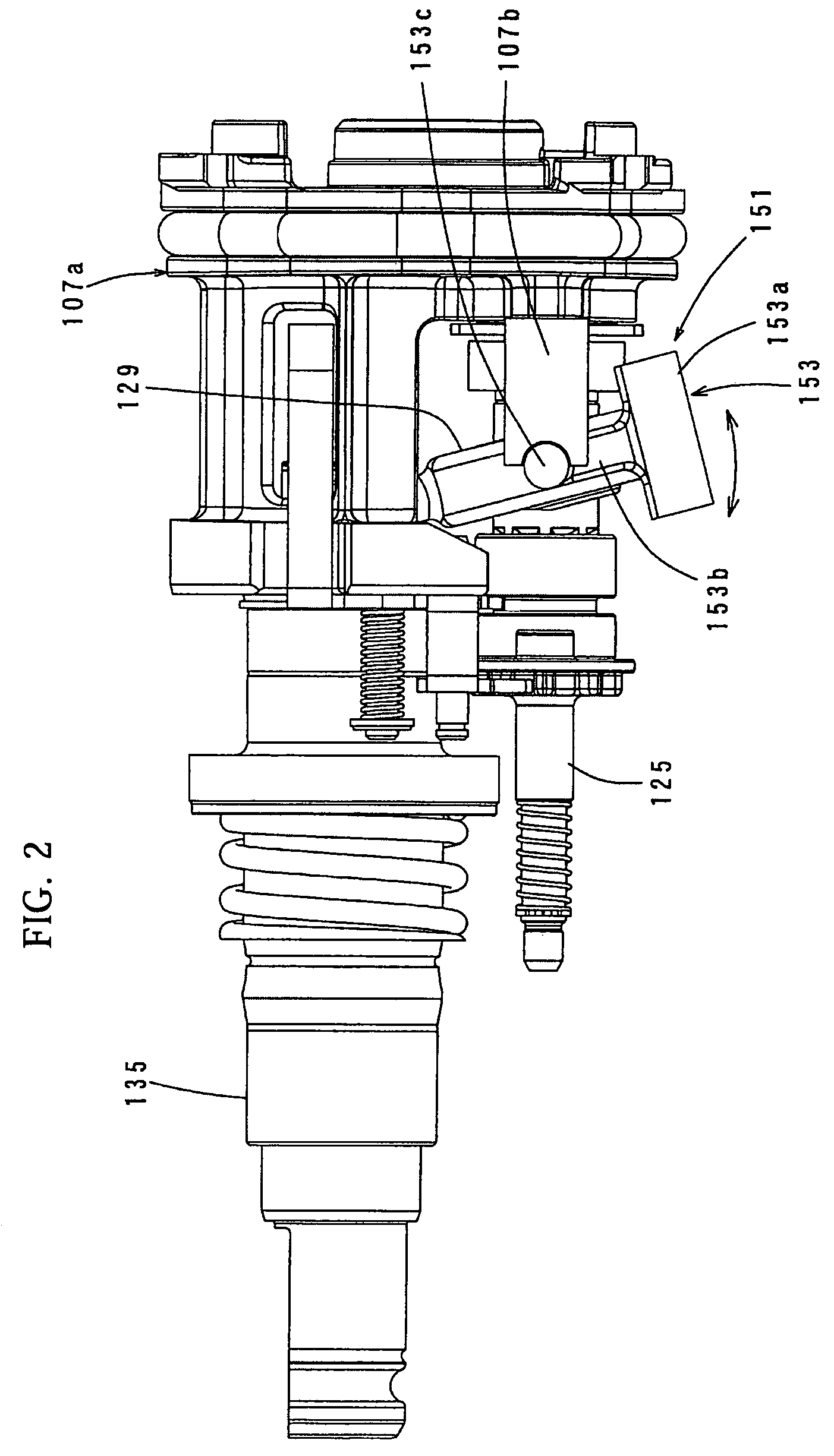
[0060]Third representative embodiment of the present invention is now explained with reference to FIGS. 8 to 14. The vibration reducing mechanism 151 according to this embodiment uses the counter weight 153 and a dynamic vibration reducer 171 together. FIGS. 8 and 9 show an internal mechanism disposed within the gear housing 107, with the dynamic vibration reducer 171 shown in section. As shown in FIGS. 8 and 9, the dynamic vibration reducers 171 are disposed within the gear housing 107. The dynamic vibration reducers 171 are disposed on the right and left sides of the axis of the hammer bit 119 in the side region of the gear housing 107 of the hammer drill 101 (see FIG. 9). The right and left dynamic vibration reducers 171 have the same construction. Further, FIG. 10 is a sectional view of the vibration reducing mechanism part, and FIG. 11 is an external view of the vibration reducing mechanism part (with the dynamic vibration reduces 171 shown in section). FIGS. 12 to 14 show the ...


PUM

PropertyMeasurementUnit
weightaaaaaaaaaa
elastic deformationaaaaaaaaaa
distanceaaaaaaaaaa

Abstract

It is an object of the invention to provide a technique for further improving the vibration reducing performance in a power impact tool that linearly drives a tool bit by using a swinging mechanism. According to the invention, a representative power impact tool is provided with a motor, a rotating shaft, a swinging member, a tool driving mechanism and a counter weight. The swinging member is supported by the rotating shaft to swing in the axial direction of the rotating shaft by rotation of the rotating shaft. The counter weight is disposed in a region higher than a lower end region of the swinging member in the vertical direction to intersect with the axis of the rotating shaft, and a lower end of the counter weight is connected to the lower end region of the swinging member. The counter weight extends upward from the connection between the counter weight and the swinging member and has a pivot point in the extending end portion, and when the swinging member swings, the counter weight is driven by the swinging member to rotate in the axial direction of the tool bit, thereby reducing vibration caused in the axial direction of the tool bit.

Description

BACKGROUND OF THE INVENTION[0001]1. Field of the Invention[0002]The present invention relates to a technique for reducing vibration in a power impact tool that linearly drives a tool bit in its longitudinal direction by a swinging mechanism[0003]2. Description of the Related Art[0004]A technique for reducing or alleviating vibration caused in an electric hammer drill with a swinging mechanism is disclosed in EP1000712. According to the known art, the swinging mechanism includes a swinging ring swinging in the axial direction of a rotating shaft by rotation of the rotating shaft driven by a motor. A tool bit is linearly driven by a tool driving mechanism connected to an upper end region of the swinging ring. In a vibration reducing mechanism in this known technique, a counter weight is connected to the lower end region in a position shifted about 180° in the circumferential direction from the connection between the swinging ring and the tool driving mechanism. The counter weight line...

Claims


Application Information

Patent Timeline
Patent Type & Authority Patents(United States)
IPC IPC(8): B25D17/00
CPCB25D11/062B25D17/24B25D2250/245B25D2217/0092B25D2217/0088
Inventor KAMEGAI, HIKARUYOSHIKANE, KIYONOBU
Owner MAKITA CORP
Why Eureka
Try Eureka