Method and apparatus for directional drilling with variable drill string rotation

a directional drilling and variable technology, applied in the direction of drilling accessories, drilling machines and methods, directional drilling, etc., can solve the problems of overloading of cutting structures, inefficient phase, and inability to control the orientation of the bit and the amount of force applied to the cutting structur

Active Publication Date: 2009-09-15
PRECISION DRILLING CORP
View PDF18 Cites 46 Cited by
  • Summary
  • Abstract
  • Description
  • Claims
  • Application Information

AI Technical Summary

Benefits of technology

[0018]Generally the effect of static friction on axially advancing of the drill string when directional drilling, as described above, is avoided by keeping the drill string rotating continuously in one direction in a manner that still allows the borehole direction to be changed in a controlled manner. During steering, the rotary speed of the drill string is varied within a revolution and substantially similarly for each of a plurality of subsequent revolutions. The drill string can be rotated very slowly when oriented at or near the desired orientation to achieve the desired change in direction and then rotated much faster during the balance of each revolution. This serves to cause a bottom hole assembly (BHA) to drill at or near the desired orientation, or an effective tool-face orientation ETFO, for a high percentage of the time it takes for each revolution. This changes the borehole orientation in the desired manner without having to confront the effects of static friction that arise when part or all of the drill string are not being rotated continuously. The position of the BHA relative to the fixed reference direction of the borehole is known. A control system can calculate a desired variable rotational velocity or angular velocity profile such that the rotary speed is varied during each revolution in a manner that the borehole is drilled at about the desired orientation. The rotary speed at any particular point in the rotation of the drill string, relative to the reference direction, can be similar for each revolution. For correcting a trajectory, the velocity profile can be shifted by a corrective angular offset for adjusting the first ETFO to a corrected, second EFTO for steering towards the desired trajectory.

Problems solved by technology

The sliding phase is necessary for adjusting or setting the direction of the borehole path, however this phase is somewhat inefficient due to factors including the indirect angular path and the friction or drag of the sliding drill string.
Overcoming the static friction to initiate movement can result in significant drill string movement and cause problems in controlling the orientation of the bit and amount of force applied on the cutting structures of the bit.
In severe cases the amount of movement of the drill string after overcoming the static friction can cause an overload on the cutting structures of the drill bit which can damage the bit, exceed the torque available to turn the bit or alter the orientation of the cutting structure so that the hole is not being curved in the desired direction.
In this manner, the drill string will be advanced in small slides at the end of each rocking sequence which is not optimal for drilling.

Method used


Image

  • Method and apparatus for directional drilling with variable drill string rotation
  • Method and apparatus for directional drilling with variable drill string rotation
  • Method and apparatus for directional drilling with variable drill string rotation

Examples


Embodiment Construction

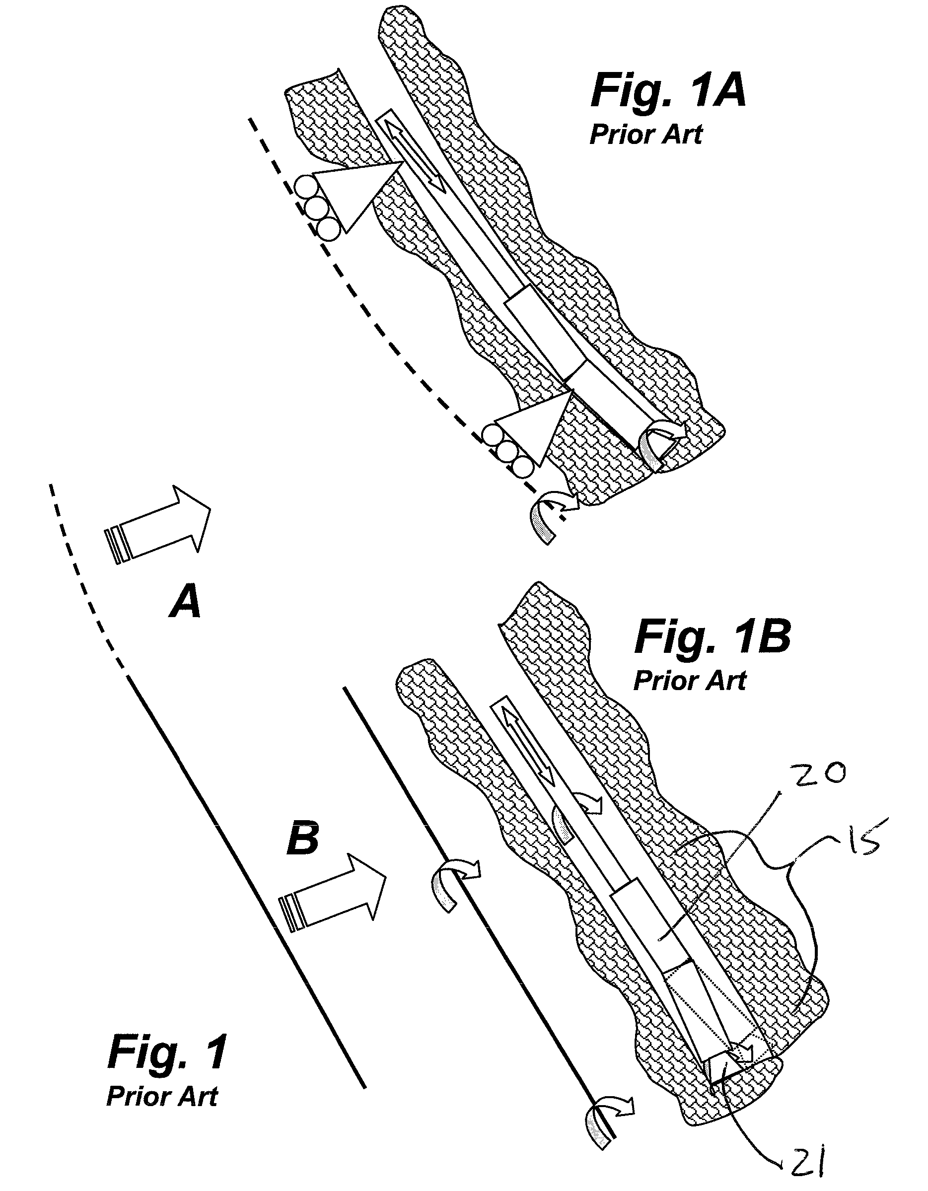
[0033]With reference to FIGS. 1,1A and 1B, a schematic of two drilling modes of the prior art illustrate, as first shown in FIGS. 1,1A, a borehole being drilled in which the drill string is non-rotating and is “sliding” while a drilling assembly, including a bent housing having a motor and a drill bit, drills the borehole along a curved path as determined by the bent housing. As shown in FIGS. 1,1B, the drill string can also be rotated continuously, continuously reorienting the bent housing for drilling a straight path having a slightly larger borehole. The desired trajectory or path of the resulting borehole is achieved using a combination of the “sliding” and rotating drilling. An operator periodically or continuously monitors the tool-face orientation such as through periodic surveys while sliding using measurement while drilling (MWD) tools. While sliding, a portion of the drilling assembly slides without rotating and MWD can be used. Conventionally, for adjustment of the boreho...


PUM


Abstract

Apparatus and methodology is provided for directional drilling which avoid the effects of static friction between the drill string and the borehole. The drill string is rotated continuously in one direction during rotating drilling and during steering. During steering, the rotary speed of the drill string is varied within a revolution and substantially similarly for each of a plurality of subsequent revolutions. The drill string is rotated very slowly when oriented at or near the desired orientation to achieve the desired change in direction and then rotated much faster during the balance of each revolution. This angular velocity profile results in drilling at or near a desired orientation for a high percentage of the time it takes for each revolution. Changes in an effective tool-face orientation can be effected by shifting the phase of the velocity profile.

Description

FIELD OF THE INVENTION[0001]The present invention relates to directional drilling of a borehole and more particularly to method and apparatus for affecting the trajectory of a borehole by continuous rotation of a drill string and varying the rotational speed within each revolution in a manner which is substantially the same for each revolution to effect steering of the borehole.BACKGROUND OF THE INVENTION[0002]Rotary drilling of a borehole beneath the surface of the earth is a practice typically used as part of an exploitation plan for transporting subsurface fluids, gases and minerals to the earth's surface. A “drill string” extends down the borehole and is suspended from a drilling rig. The drill string creates the borehole. At the distal end of the drill string is the “drill bit” or “bit” which removes material from the circular base of the borehole.[0003]The action of removing this material is usually accomplished by rotating the bit about an axis that is approximately coinciden...

Claims


Application Information

Patent Timeline
Patent Type & Authority Patents(United States)
IPC IPC(8): E21B7/04
CPCE21B7/068E21B7/06
Inventor HAMILTON, JAMES F
Owner PRECISION DRILLING CORP
Why Eureka
Try Eureka