
Injection systems

a technology of injection system and injection tube, which is applied in the field of injection system, can solve the problems of inability to find the initial hole created by the perforator to inject the anesthetic, difficulty in finding the initial hole created by the perforator, and inability to achieve the effect of reducing the chance of dislodging the tool, avoiding over torque of the tool, and improving the system and method

Inactive Publication Date: 2009-09-15
W&H DENTALWERK
View PDF39 Cites 87 Cited by
  • Summary
  • Abstract
  • Description
  • Claims
  • Application Information

AI Technical Summary

Benefits of technology

The patent text describes improved systems and methods for delivering anesthetic to patients using an intraosseous injection device. The device allows for direct delivery of the anesthetic solution to the patient's bone marrow canal, reducing the risk of injury and clogging. The device includes a tool with a solution dispensing opening and a gripping mechanism for easy handling. The system also includes a cartridge receiving mechanism for easy loading and unloading of the solution cartridge. The technical effects of the patent text include improved safety, reduced risk of injury, and more efficient and cost-effective procedures.

Problems solved by technology

Some intraosseous injection systems have disadvantages in the perforation or injection process.
Some systems require the use of at least two tools, a perforator and a separate injector needle, making the injection procedure complicated and time consuming.
With some systems, it is difficult to find the initial hole created by the perforator to inject the anesthetic.
In some cases where a guide sleeve is used, the guide sleeve can be difficult to remove.
Some systems have a needle that serves both as a perforator and an injector, however, these systems often become clogged with bone chips which can prevent the injection of the anesthetic solution.
In some systems, the tools tend to heat up during cortical plate penetration and can wear-out prematurely.
Excessive heat generated during cortical plate penetration can cause the intermediate component holding the needle or perforator to meltdown and in some cases detach from the needle or perforator.
The detached needle or perforator can lead to further complications.
In some cases, driving devices having motorized portions can break the tools by applying excessive torque to the tool.
Some intraosseous injection systems have a static needle arrangement where it is difficult and / or time consuming to replace the needle and may increase the risk of needle-prick injuries.
However, in some systems, the needle is not shielded at all times and the chances of injury still exist.
Exposure of the needle increases the chances of pricking the patient and / or the end user.

Method used


Image

  • Injection systems
  • Injection systems
  • Injection systems

Examples


Embodiment Construction

[0128]As should be understood in view of the following detailed description, this application is primarily directed to, though not necessarily limited to, a handpiece for medical applications, such as, for example, an intraosseous injection system.

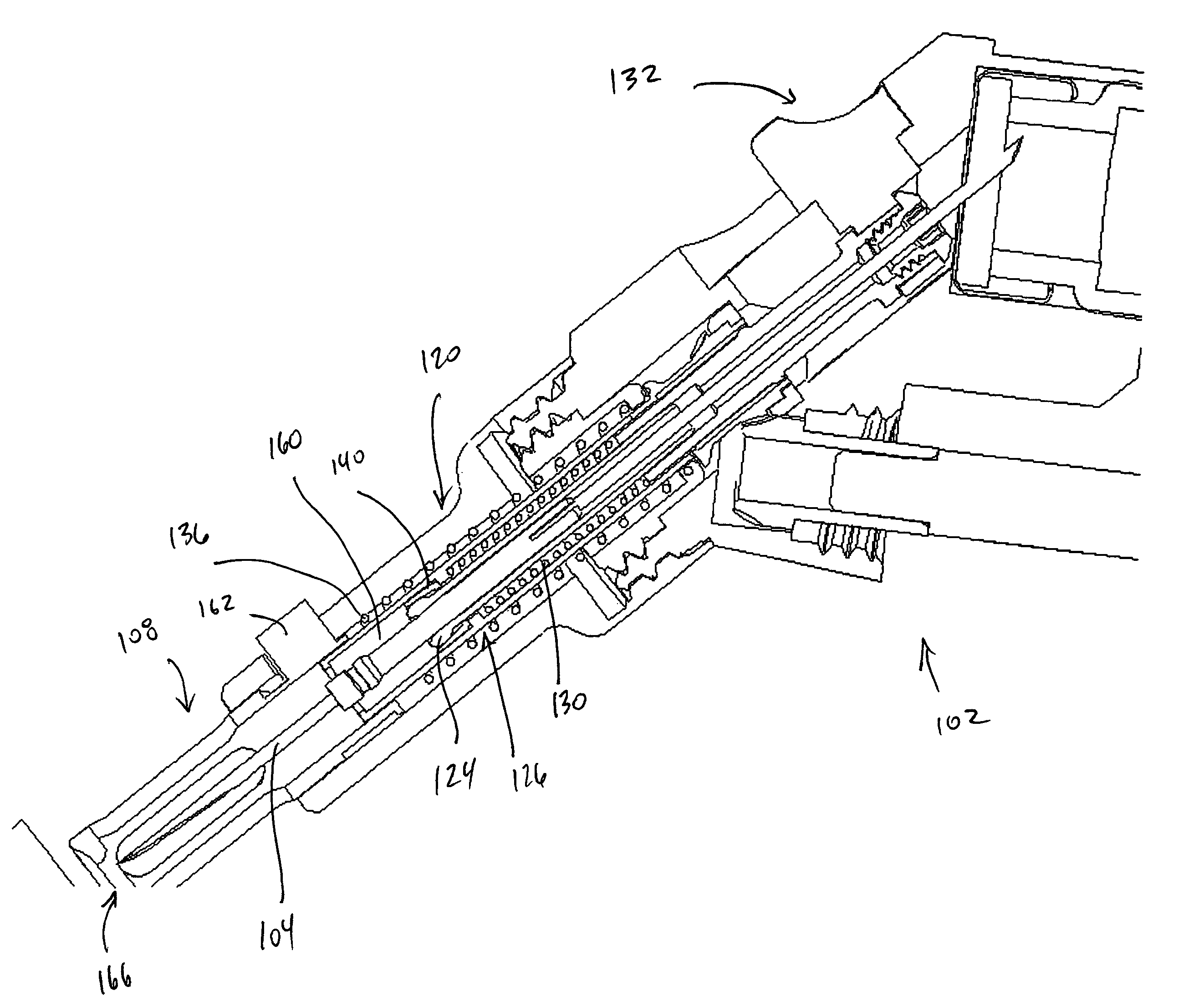
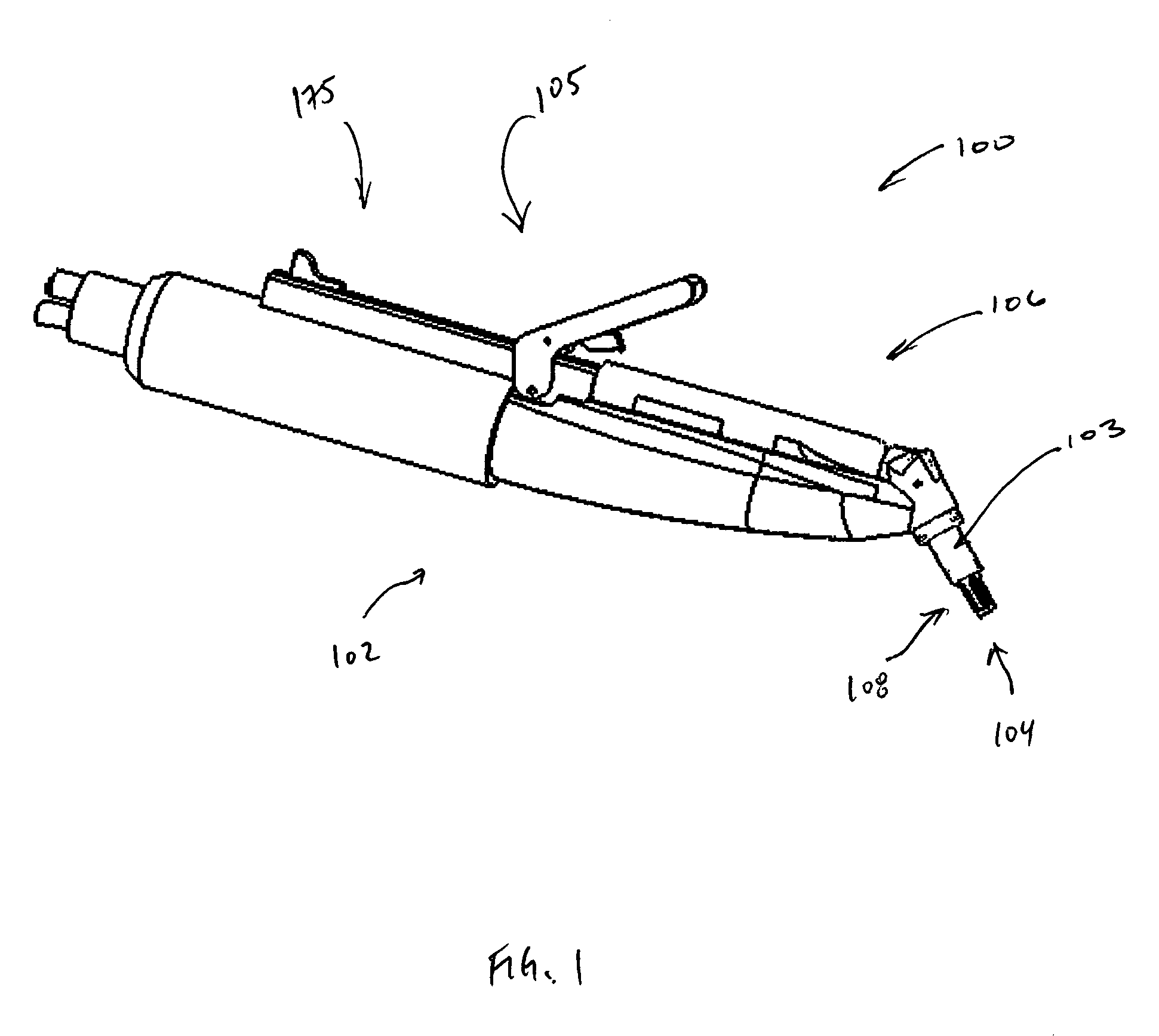
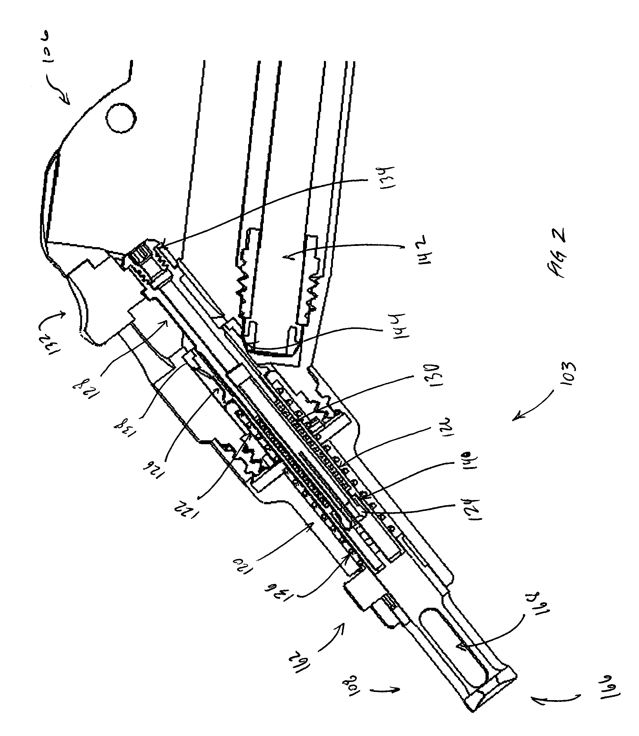
[0129]FIGS. 1-17 illustrate one embodiment of an intraosseous injection system 100. FIG. 1 is a side perspective view of the intraosseous injection system 100. The system 100 comprises a handpiece 102 having a tool actuation mechanism 103 and a solution dispensing mechanism 105. A tool 104 (see FIG. 3) is configured to be rotatably coupled to the tool actuation mechanism 103. The actuation mechanism 103 is preferably coupled to a distal portion of the handpiece 102. As will be explained in detail below, the tool actuation mechanism 103 is configured to hold the tool 104, which can be any of a variety of medical instruments, such as, for example, a needle, a file, a dispensing tip, a drill, and / or a burr.

[0130]As shown in FIG. 1, the soluti...


PUM


Abstract

An intraosseous injection device includes a tool having a distal portion, a proximal portion, and a solution dispensing opening. The distal portion has one or more cutting surfaces. The tool can be coupled with a protective carrier. The tool can be rotatably coupled to a tool actuation mechanism. A housing has a distal end and a proximal end. The housing releasably receives a solution cartridge containing a solution. A solution dispensing mechanism dispenses solution from the solution cartridge. A gripping member grips a proximal portion of the tool. A rotation device rotates the gripping member and thereby rotates the tool about an axis. The proximal portion of the tool connects directly to the solution cartridge such that solution from the cartridge can be delivered through the solution dispensing opening. The tool is configured to rotate relative to the solution cartridge.

Description

PRIORITY INFORMATION[0001]This application is based on and claims priority to U.S. Provisional Patent Applications No. 60 / 584,260 (filed Jul. 1, 2004), 60 / 584,321 (filed Jul. 1, 2004), and 60 / 645,210 (filed Jan. 19, 2005), the entire contents of each of which are hereby expressly incorporated by reference herein and made a part of this specification.BACKGROUND OF THE INVENTION[0002]1. Field of the Invention[0003]This application relates to medical instruments generally, and in particular relates to injection systems for intraosseous and or dental injection of medical solution.[0004]2. Description of the Related Art[0005]Intraosseous injection of anesthetic is a commonly used technique to provide a small amount of anesthetic solution to a localized area, such as the jawbone of a patient for a dental or endodontic procedure. In some cases, anesthetic solution is delivered in the trabecular bone rather than delivering the anesthesia to the soft tissue of the patient. Using an intraosse...

Claims


Application Information

Patent Timeline
Patent Type & Authority Patents(United States)
IPC IPC(8): A61M5/00A61B17/20A61M31/00
CPCA61B17/3472A61B17/32002A61M2005/3289A61B2019/481A61M5/3291A61B2019/304A61B2090/034A61B2090/08021
Inventor ARAVENA, INES M.KUMARABEDI, HAMID
Owner W&H DENTALWERK
Learn More