Antenna designs for multi-path environments

a multi-path environment and antenna technology, applied in the field of antenna designs, can solve the problems of many antennae being housed in materials, many unwanted reflections missing the receiving antenna, and space is characterized by much more complex boundary conditions

Active Publication Date: 2009-09-15
GUEST TEK INTERACTIVE ENTERTAINMENT
View PDF7 Cites 9 Cited by
  • Summary
  • Abstract
  • Description
  • Claims
  • Application Information

AI Technical Summary

Problems solved by technology

Such enclosed spaces are characterized by much more complex boundary conditions than those for which traditional antennae or antenna arrays were designed.
Unfortunately, conventional antennae are now being deployed under conditions which are radically different than those for which they were designed.
In addition, many antennae are housed in materials which are unsuitable for use in building or other enclosed environments in which it is necessary to keep flame spread and noxious, combustion-induced fumes to a minimum.
In addition, over long distances the angle of incidence of reflected signals will typically result in much of the unwanted reflections missing the receiving antenna.
However, these conditions do not prevail in today's low power, digital environments.
Moreover, because conventional antenna designs have little need to compensate for near field problems they are ill equipped to handle the near field disturbances common in such environments.
Unfortunately, in low power, digital systems, this characteristic results in eddy currents and hysteresis losses within the transmission cable, as well as reduced sensitivity of the receiving unit.
As mentioned above, modern considerations for digital low power RF systems typically result in less than optimal antenna placement.
This in turn results in decreased performance as well as potential damage to the attached transponder.
However, although an effective approach, many industries (e.g., hospitality, restaurant, transportation, etc.) strongly object to having antennae in view for reasons of aesthetics.
However, most indoor environments provide few good options for effective placement with traditional antenna designs.
Unfortunately, in a high multi-path environment such an increase in size is counterproductive in that a larger antenna is exposed to more of the multi-path signals in the environment.
However, though this approach is useful in managing multi-path, it does nothing for near field problems and, in fact, presents more challenges relating to near field disturbances than the use of a single antenna.
Such antenna diversity schemes also may result in a greater chance of equipment damage due to impedance mismatch.
This is often impractical in an environment which offers little space.
Antenna diversity is also a relatively expensive solution in that it requires at least two antennae and their related hardware.
However, the tradeoffs of circular polarization include a relatively large impedance matching network making the antenna susceptible to near field problems, and a wide bandwidth making the antenna susceptible to out of band interferences.
Although this method allows for a smaller antenna (thus resulting in lower antenna exposure to the multi-path environment), the increase in applied power tends to exaggerate near field problems.
However, while such an approach may be effective in reducing multi-path for some applications, it is not economically feasible for many of the most common low power, digital systems being deployed today.
In addition, MiMo designs are not particularly effective in addressing near field problems.
Finally, the processing overhead required for such techniques undesirably affects data throughput.

Method used


Image

  • Antenna designs for multi-path environments
  • Antenna designs for multi-path environments
  • Antenna designs for multi-path environments

Examples


Embodiment Construction

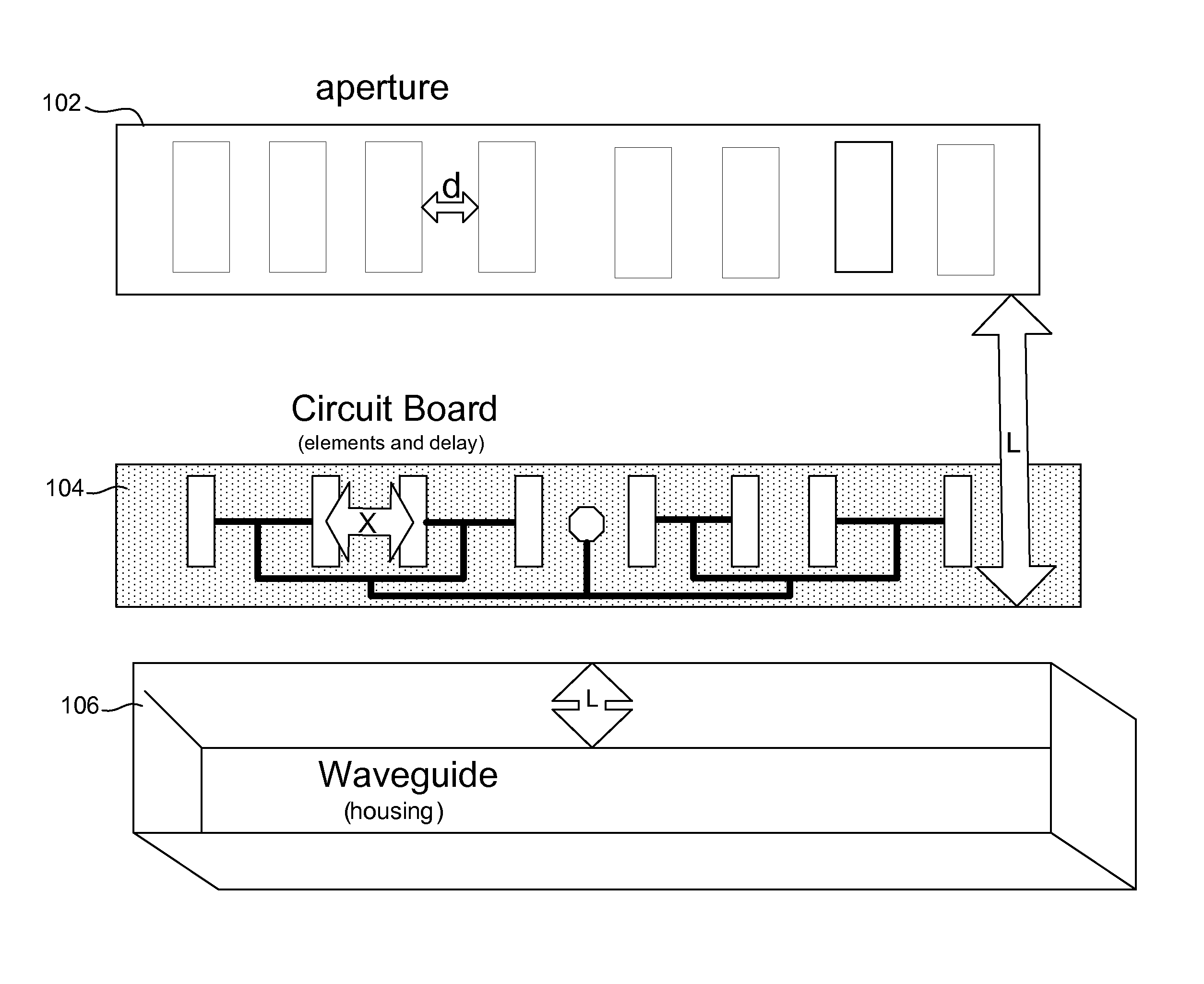
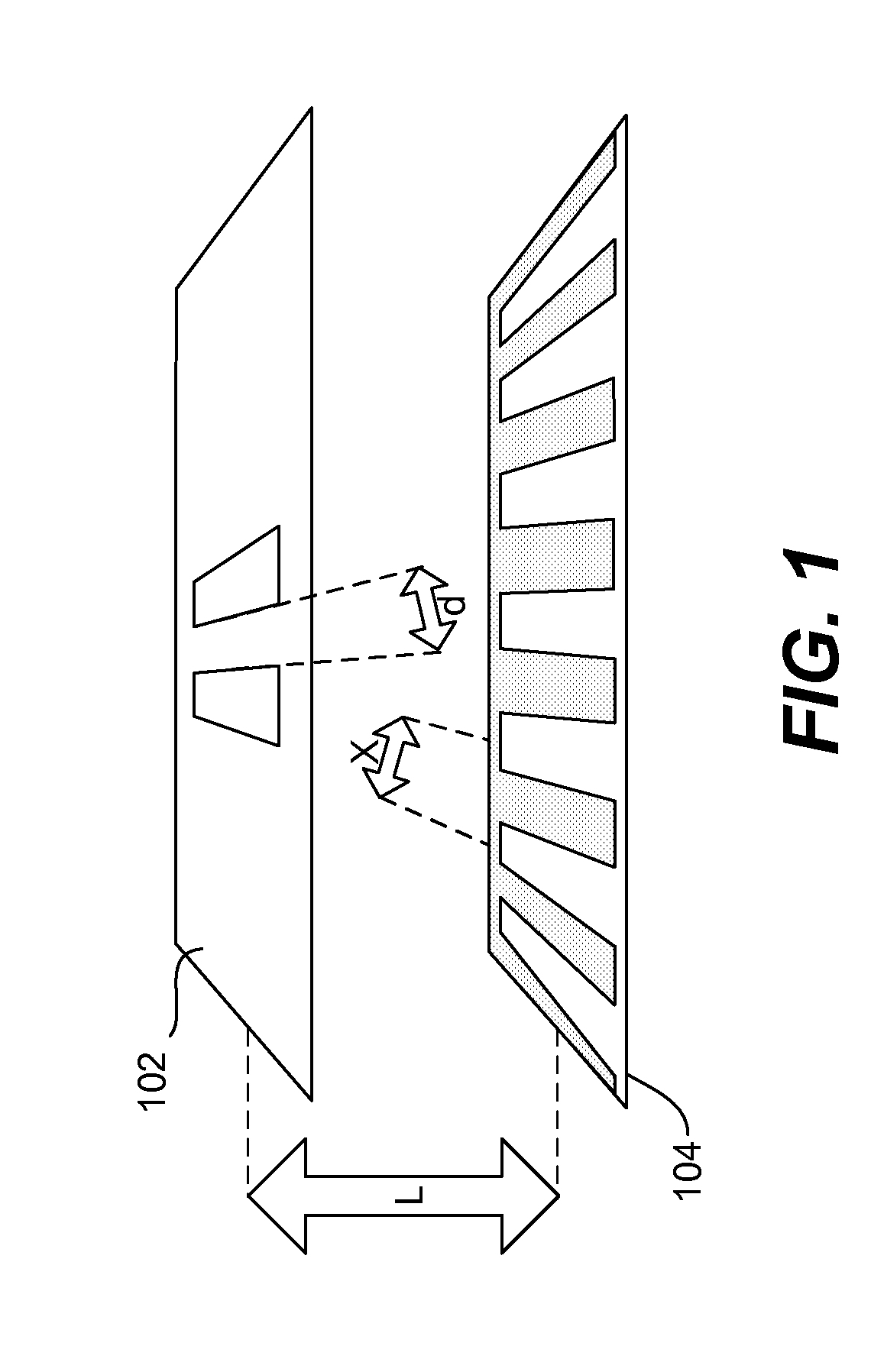
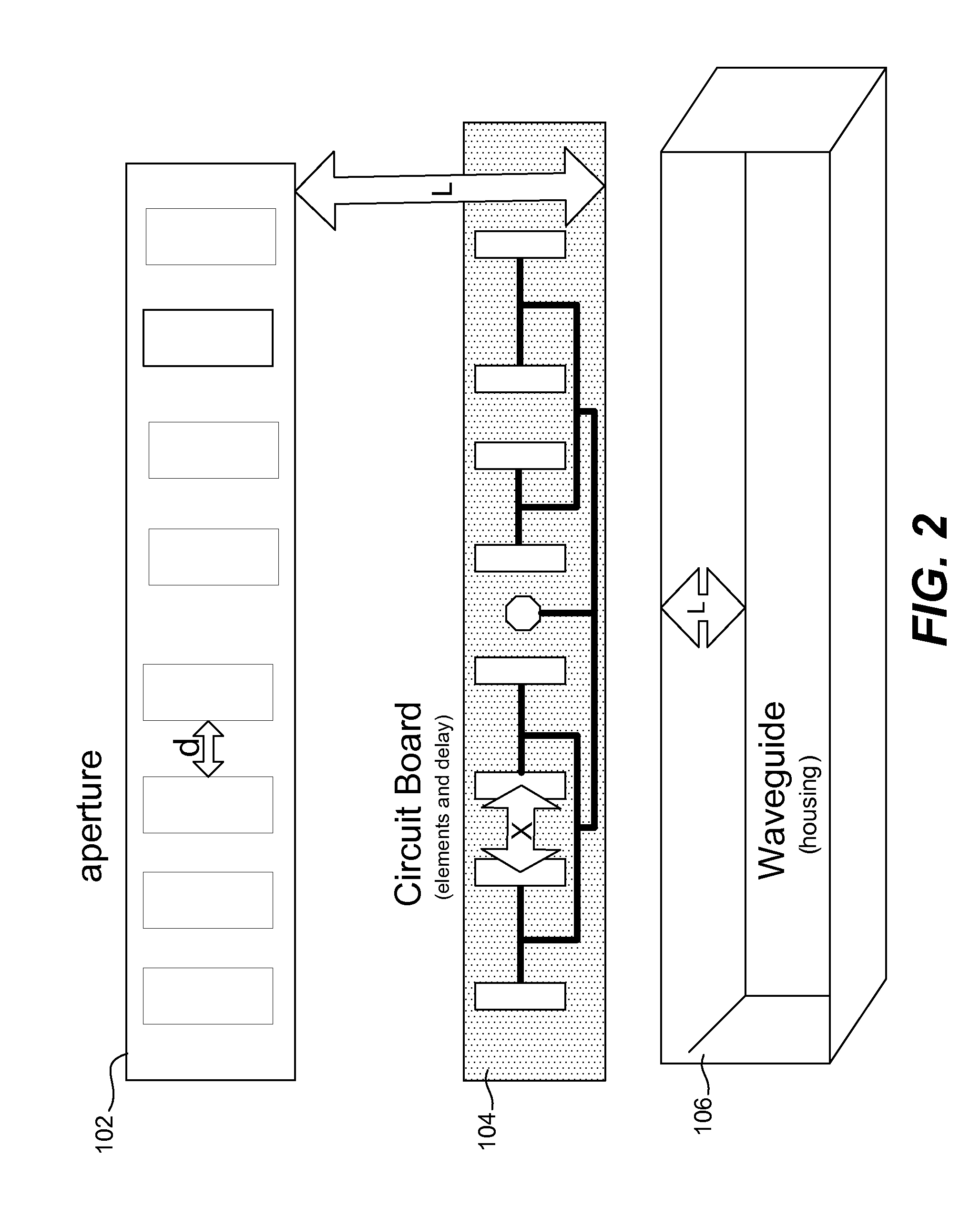
[0024]Reference will now be made in detail to specific embodiments of the invention including the best modes contemplated by the inventors for carrying out the invention. Examples of these specific embodiments are illustrated in the accompanying drawings. While the invention is described in conjunction with these specific embodiments, it will be understood that it is not intended to limit the invention to the described embodiments. On the contrary, it is intended to cover alternatives, modifications, and equivalents as may be included within the spirit and scope of the invention as defined by the appended claims. In the following description, specific details are set forth in order to provide a thorough understanding of the present invention. The present invention may be practiced without some or all of these specific details. In addition, well known features may not have been described in detail to avoid unnecessarily obscuring the invention.

[0025]Antennae designed in accordance wi...


PUM


Abstract

Antenna designs for data transmission improve signal fidelity in multi-path environments.

Description

RELATED APPLICATION DATA[0001]The present application claims priority under 35 U.S.C. 119(e) to U.S. Provisional Patent Application No. 60 / 819,030 filed on Jul. 6, 2006, the entire disclosure of which is incorporated herein by reference for all purposes.BACKGROUND OF THE INVENTION[0002]The present invention relates to antenna designs and, more specifically to antenna designs for data transmission which improve signal fidelity in multi-path environments.[0003]Only recently have modern modulation techniques, made possible by recent chipsets, enabled low power short range application of radio frequency devices to become practical or economically feasible for the transfer of high speed data in the radio frequency spectra. The relatively low power levels and high frequencies used in high speed data transfers necessitate the location of antenna close to the intended targets. Most consumer devices of this type are intended to be used at less than one hundred meters. Regulatory bodies in tu...

Claims


Application Information

Patent Timeline
Patent Type & Authority Patents(United States)
IPC IPC(8): H01Q13/10
CPCH01Q21/08H01Q13/18
Inventor WELCH, JOHN THOMASSMITH, GARY L.MINER, MARK JAMESDEHOOP, JAN M.
Owner GUEST TEK INTERACTIVE ENTERTAINMENT
Why Eureka
Try Eureka