Damped, self-cleaning flow shutoff valve and associated methods

a shutoff valve and self-cleaning technology, applied in the direction of valve operating means/releasing devices, functional valve types, transportation and packaging, etc., can solve the problems of inconvenient use of mechanical devices, inconvenient maintenance, and inability to operate properly,

Inactive Publication Date: 2009-09-22
THE ACHTERMAN REVOCABLE LIVING TRUST DATED FEBRUARY 15 2005
View PDF24 Cites 30 Cited by
  • Summary
  • Abstract
  • Description
  • Claims
  • Application Information

AI Technical Summary

Problems solved by technology

Such valves are relatively expensive because of complicated housings and / or valve elements, costly materials, and precision machining requirements.
The shutoff valves used for hydraulics, fuels and gases are out of practical range for use with appliances.
Mechanical devices have also been employed, but are complicated, expensive and / or limited in their use.
One problem that must be addressed by shutoff devices is the presence of particles and hardness in the water supply, which can accumulate to disable such valves.
Consequently, interfering deposits can build up with continued flow through the valve without actuation and result in malfunction of the valve when needed.

Method used


Image

  • Damped, self-cleaning flow shutoff valve and associated methods
  • Damped, self-cleaning flow shutoff valve and associated methods
  • Damped, self-cleaning flow shutoff valve and associated methods

Examples


second embodiment

[0017]FIG. 4 is a bottom view of a flow shutoff valve;

[0018]FIG. 5 is a cross-sectional view taken along lines 5-5 of FIG. 4;

[0019]FIG. 6 is a perspective exploded assembly view of flow shutoff valves with an appliance;

[0020]FIG. 7 is a perspective view of a flow shutoff valve with a sprinkler system;

third embodiment

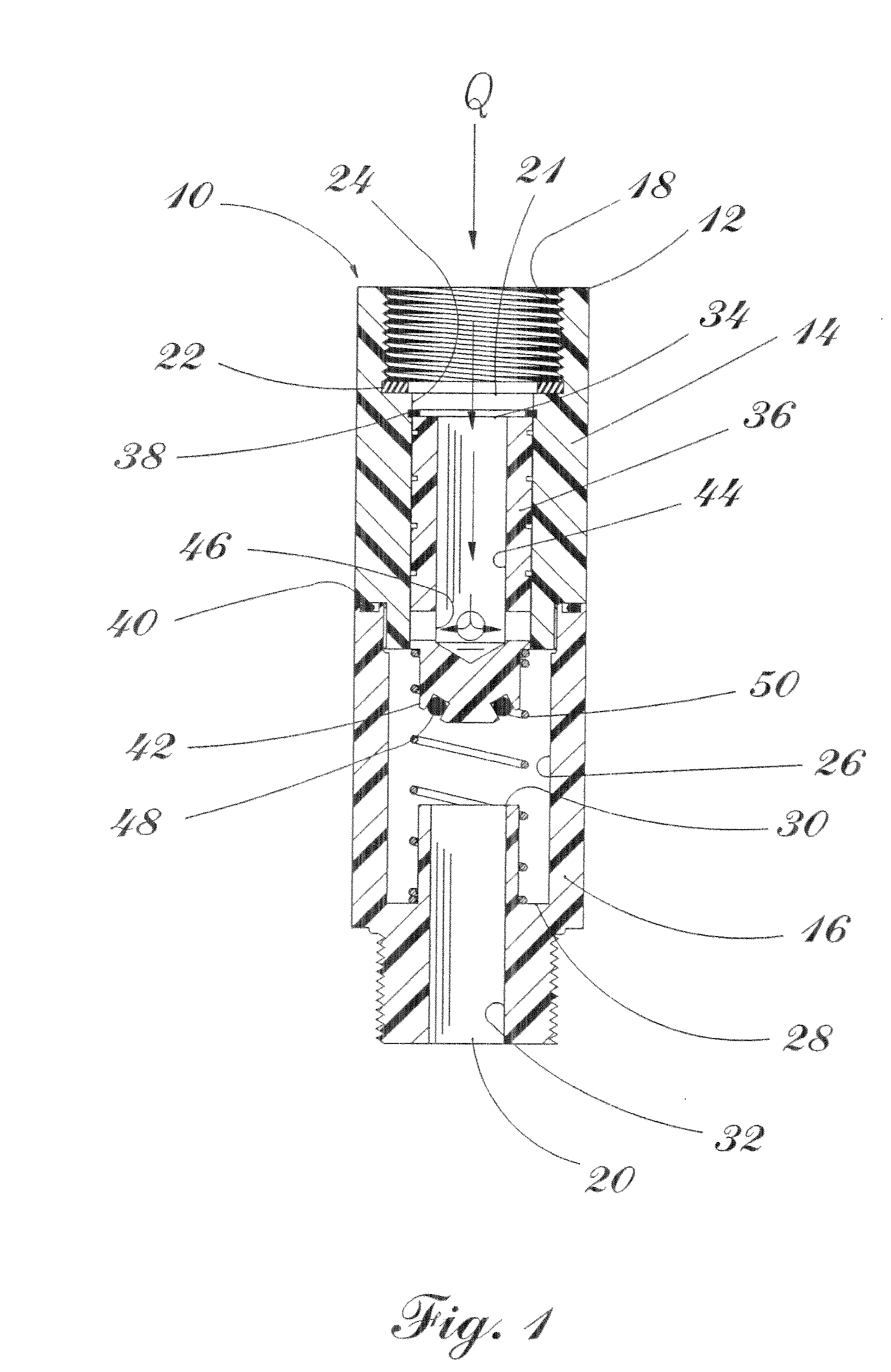
[0021]FIG. 8 is a cross-sectional view taken along the centerline of a flow shutoff valve, in a position with no flow therethrough, for use with a stop valve;

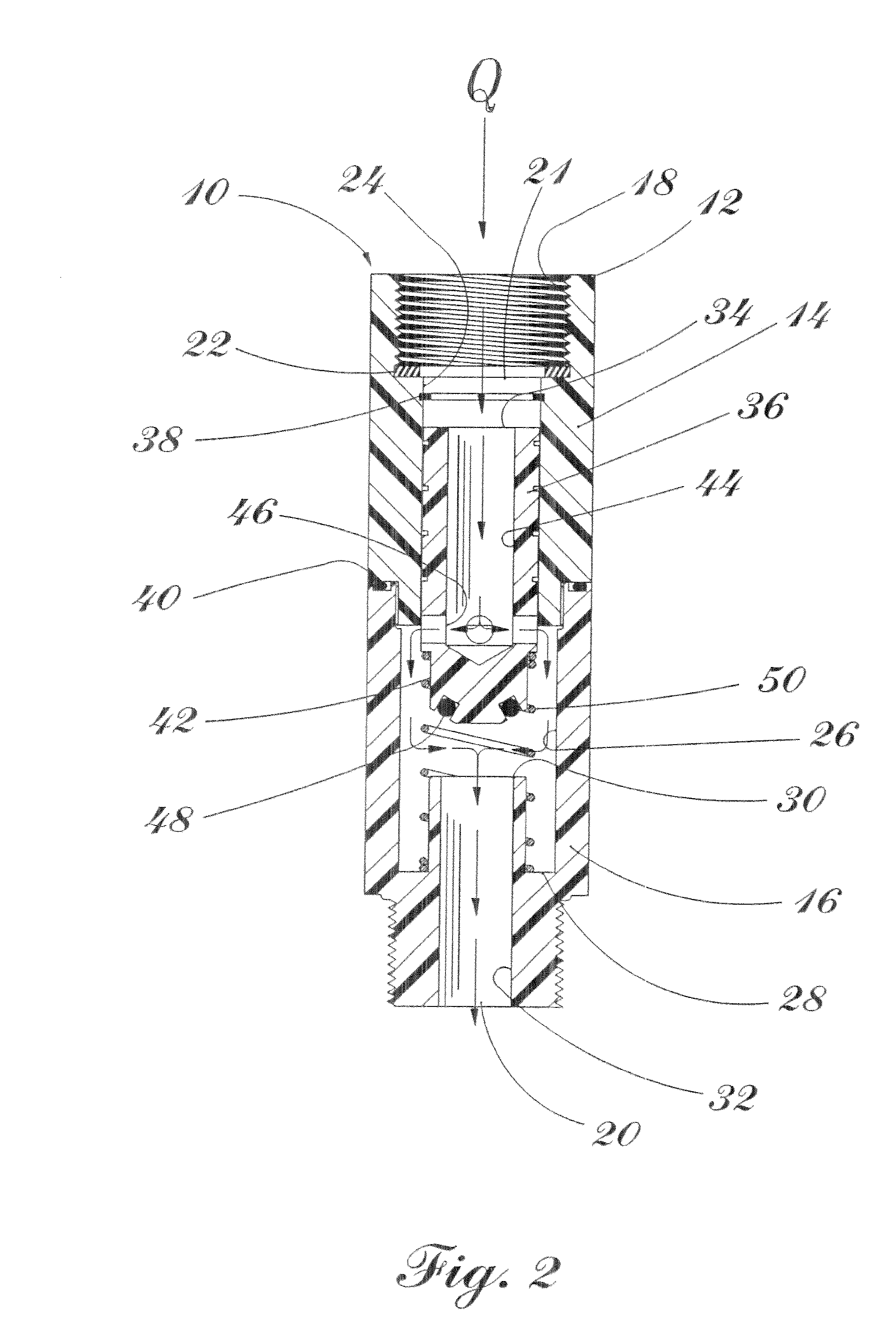
[0022]FIG. 9 is a cross-sectional view of the flow shutoff valve of FIG. 8, in an intermediate position with flow therethrough;

[0023]FIG. 10 is a cross-sectional view of the flow shutoff valve of FIG. 8, in a shutoff position;

[0024]FIG. 11 is a perspective view of a poppet guide having a plurality of metering slots therein held in the housing of the flow shutoff valve of FIG. 8;

[0025]FIG. 12 is a cross-sectional view of the combination flow shutoff valve of FIG. 8 and a stop valve, with the flow shutoff valve, in a position with no flow therethrough;

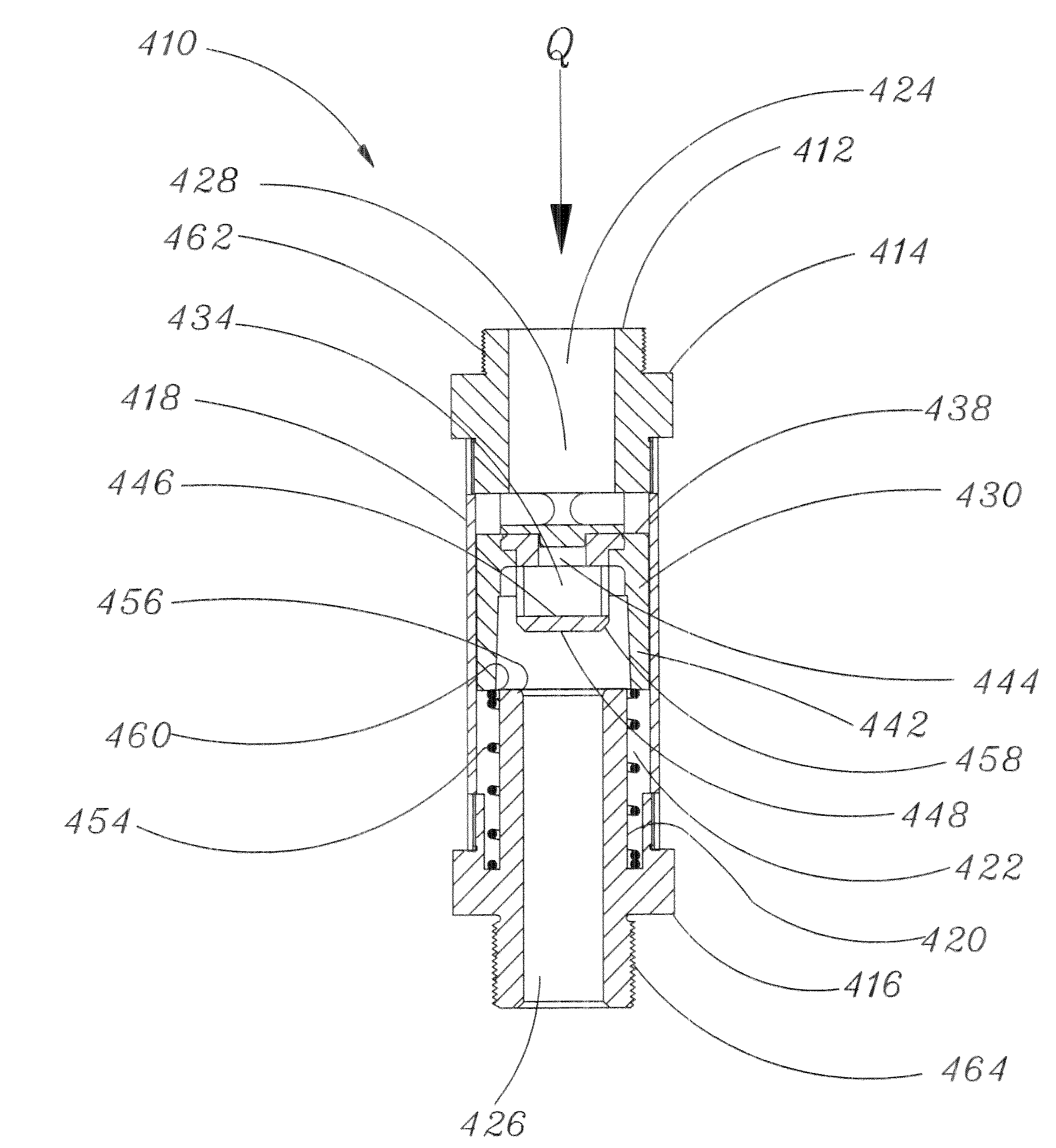
[0026]FIG. 13 is a side cross-sectional view of another embodiment of the present self-cleaning flow shutoff valve, in a position with no flow therethrough;

[0027]FIG. 14 is a side cross-sectional view of the self-cleaning flow shutoff valve of FIG. 13, in a normal flow position;

[002...

first embodiment

[0051]To accommodate the motion damper 52, the housing 12 includes an insert 60, centrally defining the cavity 54, with multiple ports 62 thereabout. The ports are substantially larger in cumulative cross-section than the orifices 46. This allows a rapid drop in pressure below the valve element 34 with resulting closure of the shutoff valve 51 when pressure at the outlet 20 drops to near zero gauge. The insert 60 may be press fit or retained by bonding. A further variation from the first embodiment may be the employment of slip sockets, as the shutoff valve 51 is depicted in FIG. 7, particularly adaptable with PVC, CPVC and ABS type piping systems for bonding of the system components to the valve 51.

[0052]FIG. 6 illustrates the use of flow shutoff valves 10 with a home appliance such as a washing machine 66. Flexible hoses 68, 70 are coupled with the flow shutoff valves 10 which are in turn coupled with the standard manual valves 64, 72. In the circumstance that a flexible hose 68, ...


PUM


Abstract

The valve comprises a housing defining a flow passage, an outer cylindrical wall, an inner cylindrical wall, and a valve seat. An annular cavity is formed between the outer cylindrical wall and the inner cylindrical wall. A valve member is slidably mounted within the housing. The valve member includes an annular skirt section extending in the downstream direction. A downstream-facing portion of the valve member comprises a sealing portion configured to selectively engage the valve seat. The valve member is movable between an upstream no flow position, a downstream shutoff position, and a normal flow position intermediate the no flow position and the shutoff position. A biasing element is disposed between the housing and the valve member so as to bias the valve member away from the valve seat. When the valve member moves from the normal flow position to the shutoff position, the annular skirt section penetrates the annular cavity and displaces water therefrom to dampen the downstream movement of the valve member.

Description

[0001]CROSS-REFERENCE TO RELATED APPLICATIONS[0002]This application is a continuation-in-part of application Ser. No. 12 / 170 / 721, filed on Jul. 10, 2008 now U.S. Pat. No. 7,503,341, which is a continuation-in-part of application Ser. No. 11 / 689,104, filed on Mar. 21, 2007, which is a continuation-in-part of application Ser. No. 11 / 535,194, filed on Sep. 26, 2006 now U.S. Pat. No. 7,552,743. The disclosures of all of the prior applications are incorporated herein by reference in their entireties.BACKGROUND[0003]1. Technical Field[0004]The present embodiments are related to flow shutoff valves for water lines, and, more specifically, self-cleaning flow shutoff valves.[0005]2. Description of Related Art[0006]Shutoff valves to prevent excess flow, such as when a sudden leak occurs downstream of the valve, are well known in the art. Such valves are found in high pressure hydraulic systems, fueling systems and critical gas systems. Such valves are relatively expensive because of complicat...

Claims


Application Information

Patent Timeline
Patent Type & Authority Patents(United States)
IPC IPC(8): F16K31/12
CPCF16K17/30Y10T137/7727Y10T137/7785Y10T137/7852
Inventor ACHTERMAN, KERMIT L.
Owner THE ACHTERMAN REVOCABLE LIVING TRUST DATED FEBRUARY 15 2005
Why Eureka
Try Eureka