Reflection optical system and projection display apparatus using the same

a technology of optical system and projection display, which is applied in the field of reflection optical system, can solve the problems of chromatic aberration inevitably occurring, magnification chromatic aberration for short-focus wide angle type, and chromatic aberration for long-focus telephoto type, and achieves the effects of less aberration, wide range of effects, and cost-effectiveness

Inactive Publication Date: 2009-09-22
FUJIFILM CORP
View PDF9 Cites 4 Cited by
  • Summary
  • Abstract
  • Description
  • Claims
  • Application Information

AI Technical Summary

Benefits of technology

[0012]The present invention has been made in view of the circumstances described above, and an object of the present invention is to provide a reflection optical system which having less aberrations and particularly being free of chromatic aberration, being cost-effective, having a wide angle, and allowing an enlargement side image surface and the position of an optical system to be close to each other in the height direction when used in a projection optical system, and a projection display apparatus using the reflection optical system.
[0013]Further, it is an object of the present invention to provide a reflection optical system with consideration also given to a focus system ensuring brightness and having a reduced performance degradation which is strongly desired as a projection optical system, and a projection display apparatus using the reflection optical system.

Problems solved by technology

However, if the refracting optical system is used, a chromatic aberration inevitably occurs because of characteristics of the optical glass.
Particularly, an on-axis chromatic aberration for the long-focus telephoto type and a magnification chromatic aberration for the short-focus wide angle type are very serious problems.
However, the optical systems described in the above five documents described above have still many serious problems for practical use as a projection optical system, such that an enlargement side angle of view is narrow, an angle formed with an enlargement side image surface is large, a reduction side luminous flux divergent angle is small, and any specific proposal for a focus system is not made.
If the enlargement side angle of view is small, a distance between the enlargement side image surface and the optical system is increased when a magnification is to be increased, and therefore upsizing of apparatuses is incurred and limitations on placement positions become severer, which is not preferable.
If the angle formed with the enlargement side image surface is large, a difference between the enlargement side image surface and the position of the optical system in the height direction increases, and therefore upsizing of apparatuses is incurred and limitations on placement positions become severer, which is not preferable.
It is difficult to put the optical system to practical use unless a specific proposal is made on what focus system is employed, e.g. how to shift which member to perform focusing.

Method used


Image

  • Reflection optical system and projection display apparatus using the same
  • Reflection optical system and projection display apparatus using the same
  • Reflection optical system and projection display apparatus using the same

Examples


example 1

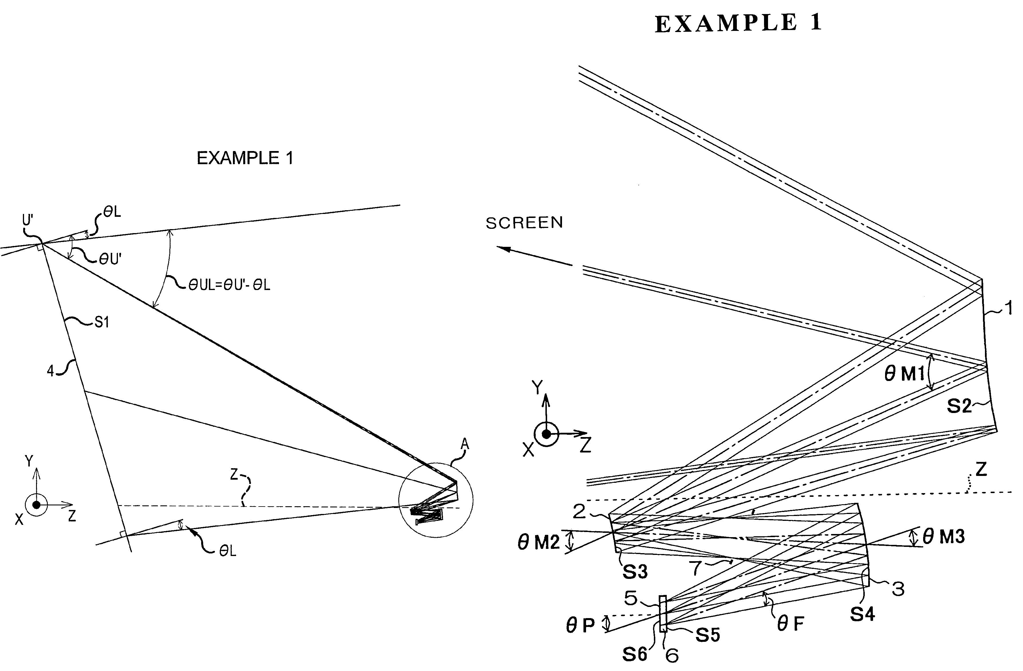
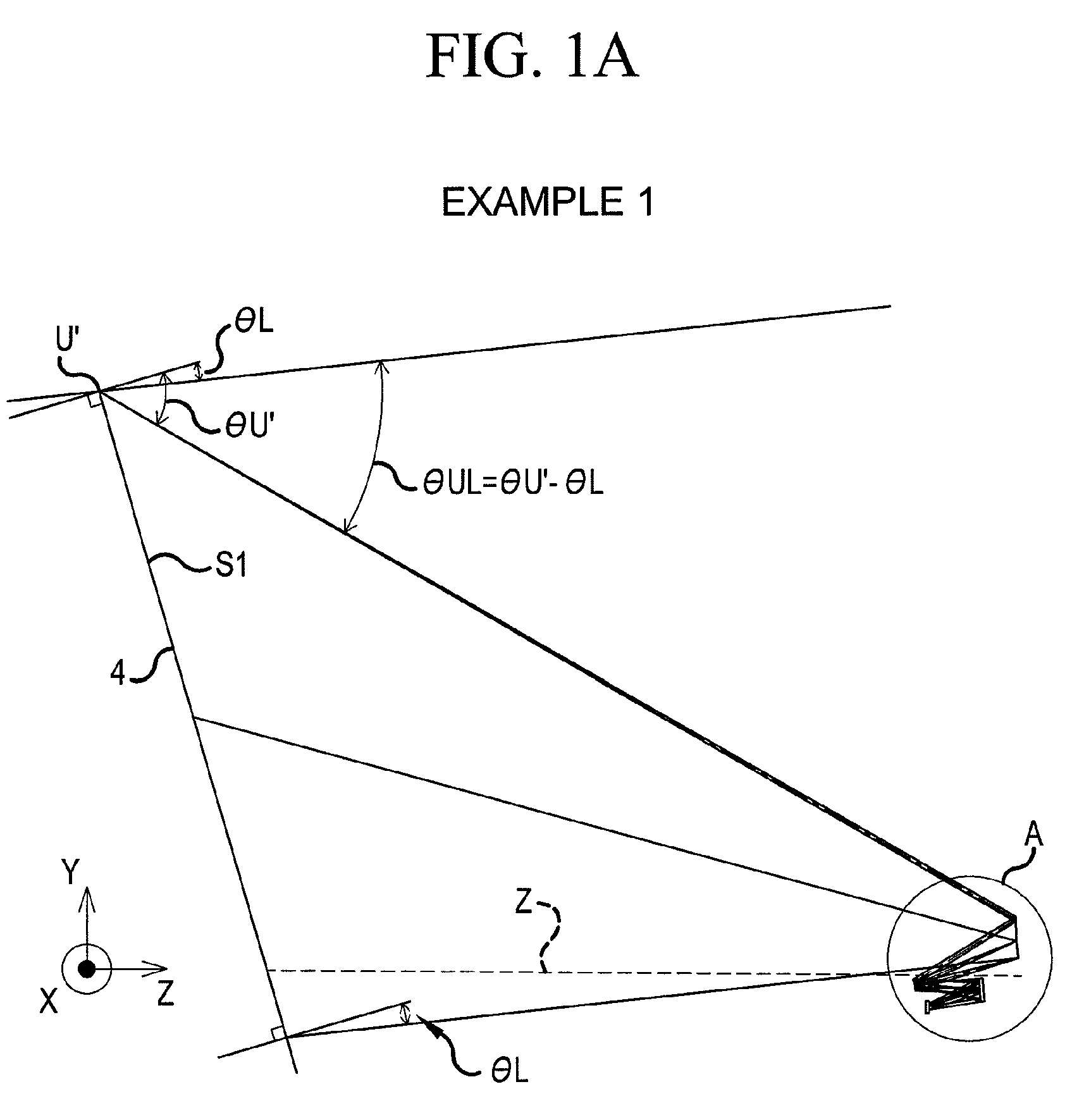
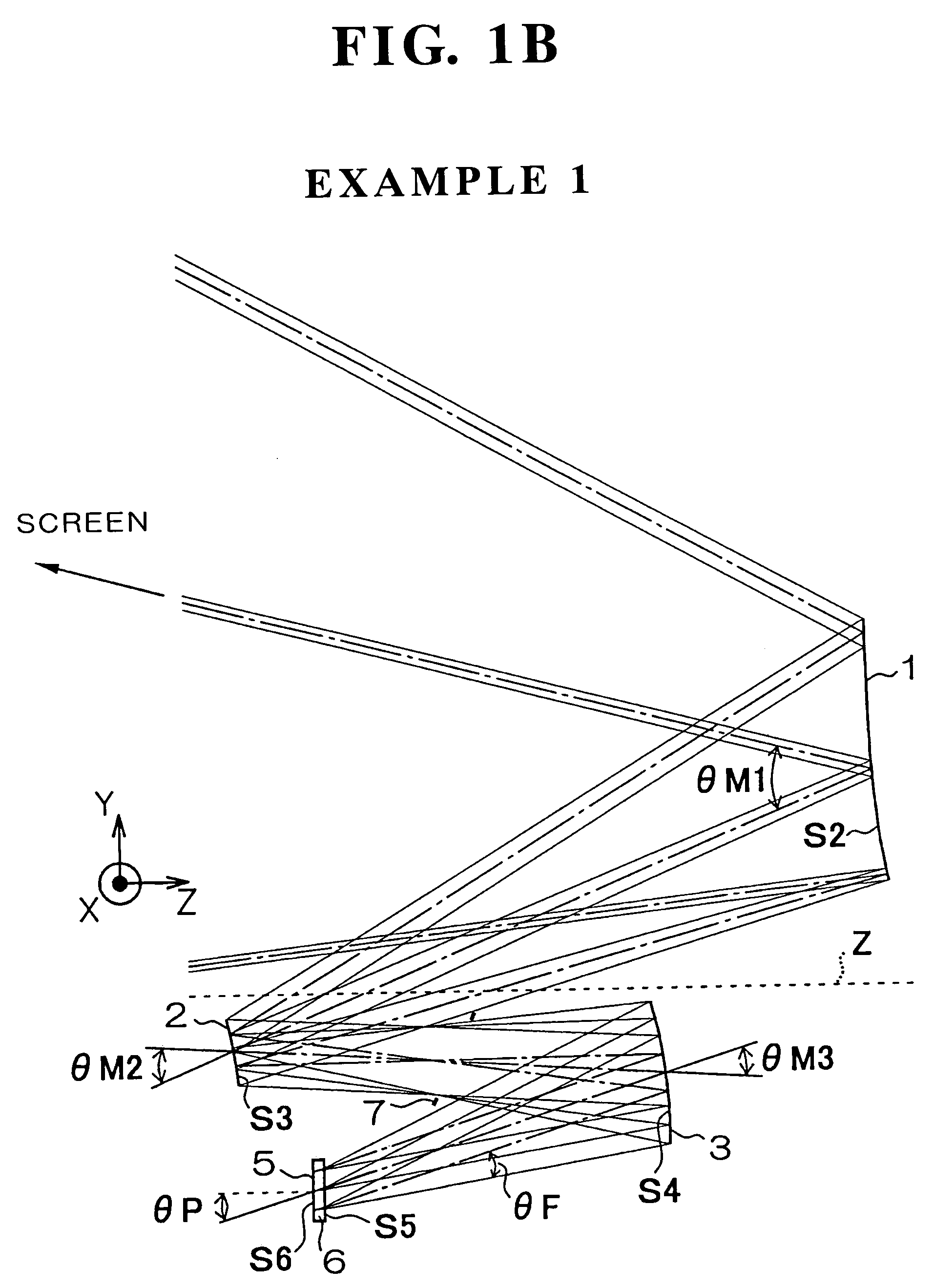
[0102]The configuration of the reflection optical system according to example 1 is shown in FIGS. 1A and 1B.

[0103]The radius of curvature of the surface of each member of the reflection optical system of example 1, the distance between surfaces of each member in the Z direction (air gap between members and central thickness of each member), and the refracting index Nd and Abbe number vd in the d line of each member are shown in Table 1-1 (described later). Surfaces with * shown on the left to the surface number are eccentric surfaces. The shift amount in the Y direction and the amount of rotation about the X axis are shown in Table 1-2 (described later) as eccentricity data of these eccentric surfaces. In this reflection optical system, the enlargement side image surface is rotated with respect to an X axis as a pivot (hereinafter referred to simply as “rotated about the X axis”), and the enlargement side image surface and the reduction side image surface are non-parallel.

[0104]The ...

example 2

[0111]An enlarged view of main parts is shown in FIG. 6 as the configuration of the reflection optical system according to example 2.

[0112]The configuration of this reflection optical system is substantially same as that of example 1, but in FIG. 6, a prism section 8 is shown instead of the cover glass, on the light exit side of the reduction side image surface. Thus, in the reflection optical system of the present invention, a plane member can be placed between the reduction side image surface and the enlargement side image surface. For example, if a cross dichroic prism for color combining or the like is placed as described later, the cover glass and the cross dichroic prism placed on the light exit side of the light valve 5 placed on the reduction side image surface correspond to the prism section 8.

[0113]The focus operation of this example is based on the second system described above. The shift trail of the first mirror 1 forms a straight line. In this example, two focus shift ...

example 3

[0120]An enlarged view of main parts is shown in FIG. 7 as the configuration of the reflection optical system according to example 3.

[0121]The configuration of this reflection optical system is substantially same as that of example 1.

[0122]The focus operation of this example is based on the second system described above. The shift trail of the first mirror 1 forms a straight line. In this example, two focus shift positions of the focus 1 and the focus 2 are set.

[0123]The reduction side pupil position of this example is at an infinite distance, and is the above-mentioned first position. This reflection optical system is configured so that light beams of pupil center from points on the reduction side image surface intersect between the second mirror 2 and the third mirror 3, and a diaphragm is preferably placed at such a position.

[0124]In this reflection optical system, the enlargement side image surface is rotated about the X axis, and the enlargement side image surface and the reduc...


PUM

PropertyMeasurementUnit
aspect ratioaaaaaaaaaa
angleaaaaaaaaaa
anglesaaaaaaaaaa

Abstract

A reflection optical system placed between a light valve 5 and a screen 4, wherein curved surfaces are only three reflection surfaces of first to third mirrors 1 to 3, and satisfies the following:(1) θL<20 degrees, (2) 25 degrees<θUL<55 degrees, (3) 20 degrees<θM1<55 degrees, (4) 15 degrees<θM2<50 degrees, (5) 8 degrees<θM3<30 degrees, (6) θL<15 degrees, (7) 30 degrees<θUL and (8) 7.5 degrees<|θF|,where θL: minimum angle which a light beam of pupil center forms with respect to the enlargement side image surface; θUL: difference between maximum and minimum angles which a light beam of pupil center forms with respect to the enlargement side image surface; θM1, θM2 and θM3: deviation angles of the light beam of pupil center passing the center of the reduction-side image surface in first to third mirrors 1 to 3; and θF: reduction-side pupil divergent angle.

Description

RELATED APPLICATIONS[0001]This application claims the priority of Japanese Patent Application No. 2004-380690 filed on Dec. 28, 2004, which is incorporated herein by reference.BACKGROUND OF THE INVENTION[0002]1. Field of the Invention[0003]The present invention relates to a reflection optical system applicable to a projection optical system or a image optical system which is used in a camera using an image pickup device such as a CCD or image pickup tube and a film, and particularly to a reflection optical system suitable for a projection optical system projecting display information of a light valve under magnification, and a projection display apparatus using the reflection optical system.[0004]2. Description of the Prior Art[0005]In projection optical systems of projection display apparatuses and projection television apparatuses, refracting optical systems using an optical glass, and optical systems having a refracting optical system and a mirror in combination are widely known,...

Claims


Application Information

Patent Timeline
Patent Type & Authority Patents(United States)
IPC IPC(8): G03B21/28G02B5/08G02B5/10G02B7/182H04N3/14H04N9/31H04N5/74G03B21/56G02F1/00G03B21/14G03B21/26G02B17/00
CPCG02B17/0642
Inventor YAMAMOTO, CHIKARA
Owner FUJIFILM CORP
Why Eureka
Try Eureka