Apparatus and method for use of optical system with a plasma processing system

a plasma processing and optical system technology, applied in the field of plasma processing, can solve the problems of expensive and time-consuming operation

Inactive Publication Date: 2009-09-22
TOKYO ELECTRON LTD
View PDF16 Cites 16 Cited by
  • Summary
  • Abstract
  • Description
  • Claims
  • Application Information

AI Technical Summary

Benefits of technology

[0013]These and other aspects will be achieved by the invention wherein the contamination of the window between the plasma processing chamber and the optical system is monitored. Further, these and other aspects and features of the invention will become apparent from the following detailed description considered in conjunction with the accompanying drawings. It is to be understood, however, that the drawings are for the purpose of illustration only, and not as a definition of the limits or principles of the invention.

Problems solved by technology

Although this method is widely used and has been quite successful, it is problematic when the window becomes clouded because the optical diagnostic data can be skewed and even can be rendered invalid.
In addition, the window would need to be cleaned or else replaced before more product can be processed, either being an expensive and time consuming operation.

Method used


Image

  • Apparatus and method for use of optical system with a plasma processing system
  • Apparatus and method for use of optical system with a plasma processing system
  • Apparatus and method for use of optical system with a plasma processing system

Examples


Embodiment Construction

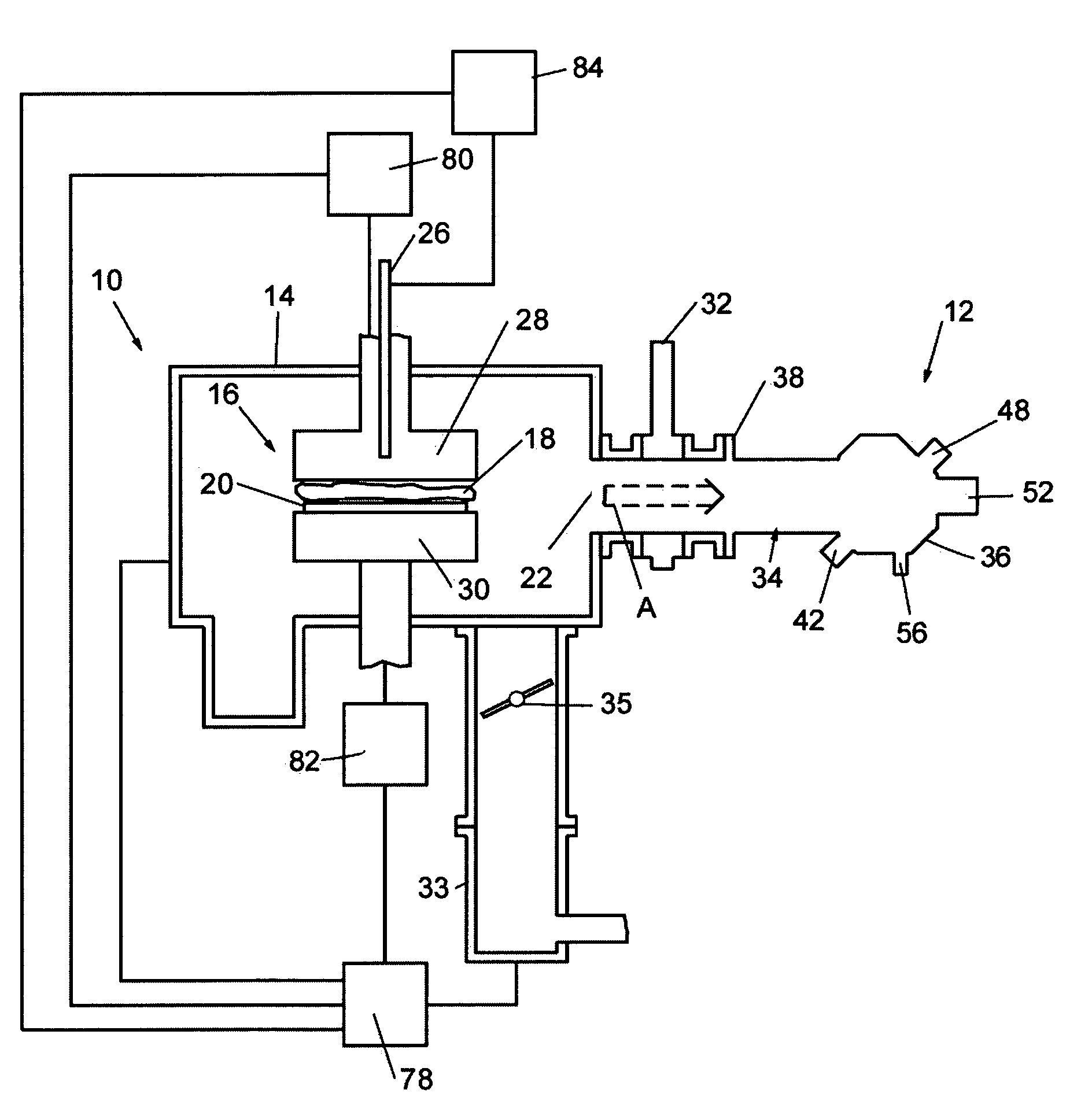
[0022]FIG. 1 shows an embodiment of a plasma processing system according to principles of the invention. The plasma processing system, generally indicated at 10, is in communication with an optical system, generally indicated at 12.

[0023]The plasma processing system 10 comprises a plasma process chamber, generally indicated at 14, that defines a plasma processing region 16 in which a plasma 18 can be generated. A chuck or electrode 30 can be positioned in the chamber 14 and is constructed and arranged to support a substrate 20, which may be a semiconductor wafer, for example, within the chamber 14 in the processing region 16. The substrate 20 can be a semiconductor wafer, integrated circuit, a sheet of a polymer material to be coated, a metal to be surface hardened by ion implantation, or some other semiconductor material to be etched or deposited, for example.

[0024]Although not shown, coolant can be supplied to the chuck 30, for example, through cooling supply passages coupled to t...


PUM

PropertyMeasurementUnit
angleaaaaaaaaaa
poweraaaaaaaaaa
areaaaaaaaaaaa

Abstract

A plasma processing system and method for operating an optical system in conjunction with a plasma processing system are provided. The plasma processing system includes an optical system in communication with a plasma processing chamber of the plasma processing system. The optical system has a window and is constructed and arranged to detect a plasma process condition through the window and a transmission condition of the window. The method includes detecting an optical emission from the plasma processing region and monitoring contamination of a window provided by the optical system.

Description

[0001]This is a continuation of International Application No. PCT / US03 / 26208, filed Aug. 21, 2003, which relies for priority upon U.S. Provisional Application No. 60 / 414,348, filed Sep. 30, 2002, the contents of both of which are incorporated herein by reference in their entireties.[0002]This continuation of PCT application is also related to International Application No. PCT / US03 / 30051, filed Sep. 25, 2003, which relies for priority upon U.S. Provisional Application No. 60 / 414,349, filed Sep. 30, 2002, the contents of both of which are incorporated herein by reference in their entireties.BACKGROUND OF THE INVENTION[0003]1. Field of Invention[0004]The present invention relates to plasma processing and more particularly to monitoring of the plasma processing using an optical system.[0005]2. Description of Background Information[0006]Typically, plasma is a collection of species, some of which are gaseous and some of which are charged. Plasmas are useful in certain processing systems f...

Claims


Application Information

Patent Timeline
Patent Type & Authority Patents(United States)
IPC IPC(8): G01L21/30H01J37/32H05H1/00
CPCH01J37/32972H01J37/32935H01J37/3211H01J37/32532
Inventor MITROVIC, ANDREJ SLUDVIKSSON, AUDUNN
Owner TOKYO ELECTRON LTD
Why Eureka
Try Eureka