System and method for multiplexing traffic signals and bridge collapse detection

a traffic signal and multiplexing technology, applied in the field of transportation signaling, can solve the problems of failing to notify motorists, waste of power supply in each signal lamp, and disable all beacons, and achieve the effects of simple rectifier and battery charger, waste of power supply in each signal lamp, and low cos

Inactive Publication Date: 2009-09-22
MARSHALL ROBERT A +1
View PDF4 Cites 2 Cited by
  • Summary
  • Abstract
  • Description
  • Claims
  • Application Information

AI Technical Summary

Benefits of technology

[0007]LED signals already employ active controls; each signal lamp includes a power supply to provide the proper illumination. In a beacon with one to three lamps, since only one signal is ever illuminated at any given time, a power supply in each signal lamp is wasteful. In accordance with the present invention, the output of the beacon's only power supply is directed to the appropriate signal lamps with a single decoded command from the traffic signal controller. The command is included on the same pair of wires as power, and only a single pair of wires is required to operate an entire intersection with turn lanes in all directions. For a four-way intersection with turn lanes, the thirty-five useful states of signal illumination are encoded, for example, with the polarity of the applied power and a single Dual Tone Multi Frequency digit. DTMF encoding takes advantage of very low-cost ICs from the telecom industry. Also, with LED signals, a low-voltage DC may be supplied to the signals, eliminating the inherent hazards with high-voltage AC and allowing the use of cheaper low-voltage wiring, such as telephone drop wire. This also allows a UPS to be replaced with a simpler rectifier and battery charger, eliminating the cost, power loss, and possible failure of an inverter.
[0008]This multiplexing method is also particularly useful in a bridge collapse detection and motorist warning system. Unnecessary loss of life and property can be significantly reduced with a reliable system to immediately and effectively detect and warn of a failed structure. A series of flashing red traffic signal beacons are spaced along a bridge to warn any motorist approaching or on the bridge of the impending peril. If all of the beacons are simply wired in parallel, any electrical fault on the wire will disable all beacons and fail to notify motorists. A collapsing bridge has the potential to fault the wiring during collapse. Home-run wiring eliminates this concern, as a short on any one beacon will not affect the others. This system only requires flashing red signals. Only three states are needed, so only polarity encoding is adequate. A single pair of wires may be routed to each beacon, containing two signal lamps. This saves one pair of wires per beacon, which can become very significant on mile-long causeways. The use of low-voltage DC allows the use of telephone drop wire, which does not need to be run in conduit, and eliminates the hazard of accidentally coming into contact with shredded power conductors after a collapse.
[0009]The same pairs of wire used to control the signals may also be used as a collapse detection sensor. This same or a separate pair of wires is monitored for the presence of an applied very low voltage at the opposite end of the bridge. Electrical continuity indicates that the bridge is still intact. This applied voltage must be low enough to not illuminate the signals on this same pair of wires. Alternately, a pair of wires may transmit a data signal, with loss of data indicating a bridge collapse. The cable must be periodically anchored to the bridge in a manner to ensure that the falling bridge will sever the cable, not simply allow it to stretch without breaking. This is of particular concern on low-rise causeways. Metallic cable is ductile and is manufactured by drawing, a controlled stretching process. At each anchor point, the metallic cable is strain-relieved and loosely spindled around a dull edge. The strain relief prevents any wear on the cable from the dull edge. In the event of a collapse, there is enough force on the metallic cable to pull out of the strain relief and be severed against the dull edge that it is now in full contact with.

Problems solved by technology

In a beacon with one to three lamps, since only one signal is ever illuminated at any given time, a power supply in each signal lamp is wasteful.
If all of the beacons are simply wired in parallel, any electrical fault on the wire will disable all beacons and fail to notify motorists.
A collapsing bridge has the potential to fault the wiring during collapse.

Method used


Image

  • System and method for multiplexing traffic signals and bridge collapse detection
  • System and method for multiplexing traffic signals and bridge collapse detection
  • System and method for multiplexing traffic signals and bridge collapse detection

Examples


Embodiment Construction

[0017]Embodiments of the present invention and their advantages are best understood by referring to FIGS. 1 through 5 of the drawings, in which like numerals refer to like parts.

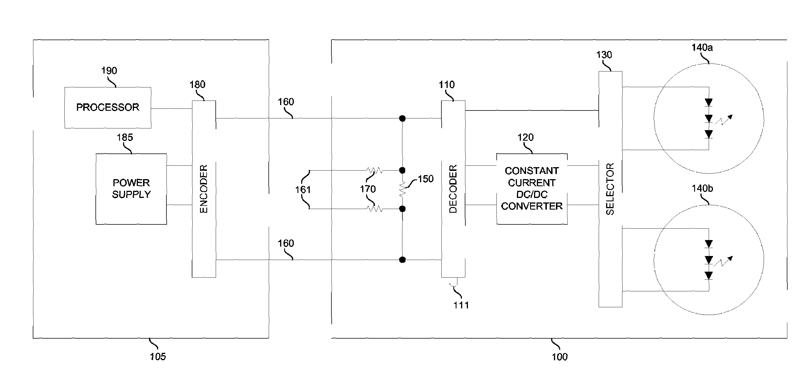
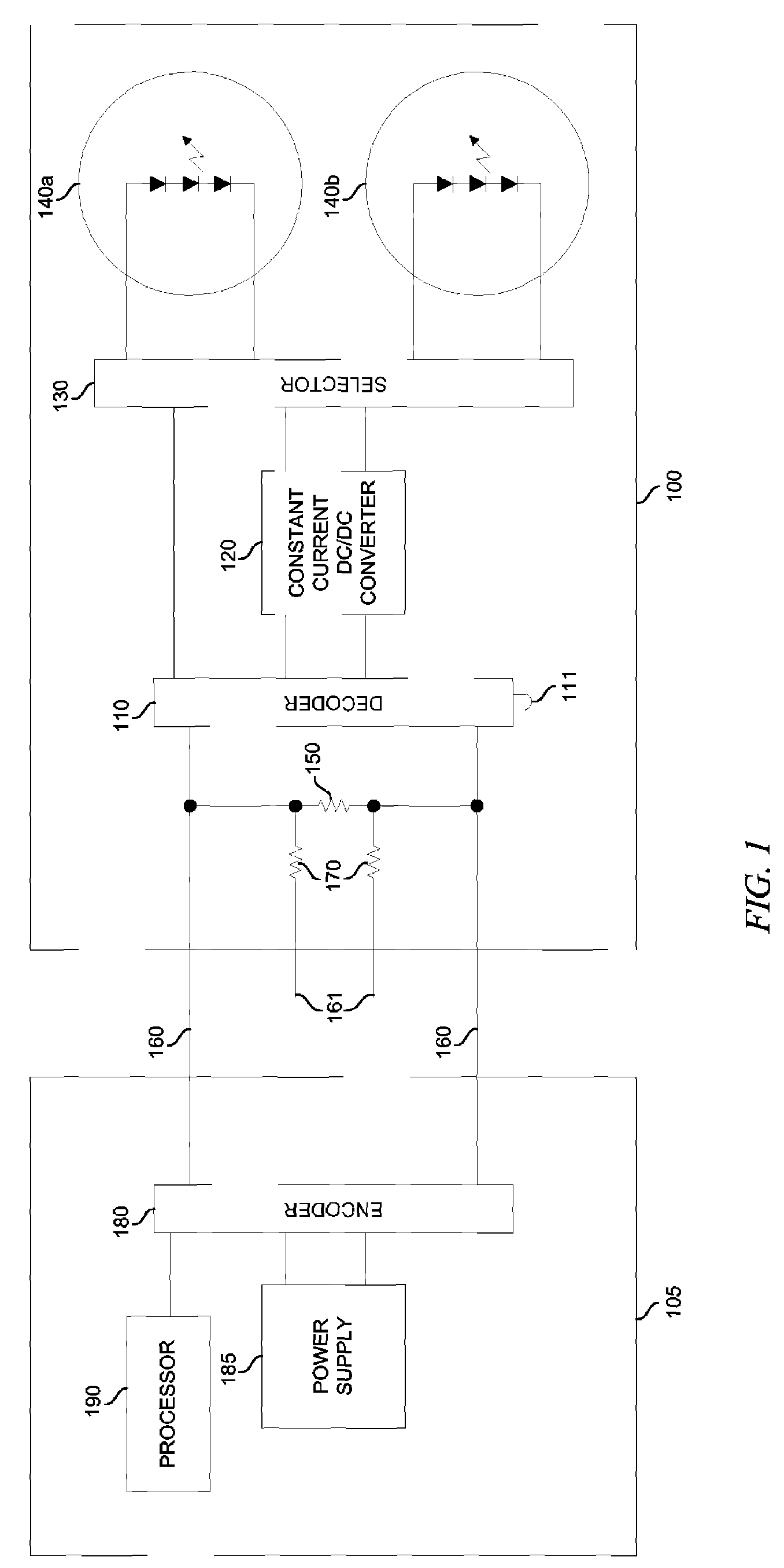
[0018]FIG. 1 shows a diagram of one embodiment of a system for controlling traffic signal beacons. A traffic signal controller 105 contains a processor 190 which selects a desired state of a multitude of traffic signal lamps 140 to control the flow of motor vehicles in a desired fashion. A single logical state transmitted over a single pair of wires 160 describes the desired traffic flow for the entire intersection. Power supply 185 provides low-voltage DC power to operate traffic lights 140a-b. Power supply 185 may also include a backup battery. Encoder 180 encodes the desired state and also couples DC power to cable 160. Encoding of three states (top lamp on, bottom lamp on, and no lamp on) is possible using only the polarity of the applied power (positive, negative, and off). Any other encoding method is ...


PUM


Abstract

A system and method for controlling transportation traffic signal beacons including powering a signal, encoding a signal state, and decoding the signal state at the beacon is presented. Furthermore, traffic signal beacons may be placed along the length of a bridge to warn of a bridge collapse. The metallic cable that powers the beacons may also function as a bridge collapse detection sensor.

Description

TECHNICAL FIELD OF THE INVENTION[0001]This invention relates generally to the field of transportation signaling and, more specifically, to a system and method of powering and controlling traffic signals. The invention is further expanded to include a bridge collapse detection systemBACKGROUND OF THE INVENTION[0002]Traffic flow control allows safe and efficient travel for motorists. At a typical automotive intersection, motorists traveling in opposing directions are given alternating rights-of-way via a set of standardized traffic signal beacons. Each beacon consists of a recognizable combination of green, yellow, and / or red electric signal lamps enclosed in a standard housing. These beacons face the desired directions of travel and are controlled from a common point with one traffic signal controller. All lamps are electrically home-run to the controller using 120VAC or other high-voltage AC power. The controller selects which lamps to illuminate at any given time while a conflict m...

Claims


Application Information

Patent Timeline
Patent Type & Authority Patents(United States)
IPC IPC(8): G08G1/095
CPCG08G1/07G08G1/096783
Inventor MARSHALL, ROBERT AMARSHALL, FRED R
Owner MARSHALL ROBERT A
Why Eureka
Try Eureka