Optical devices for guiding illumination
a technology of optical guiding devices and illumination, which is applied in the direction of fixed installations, lighting and heating apparatus, instruments, etc., can solve the problems of inefficient use of total internal reflection by light directing optical elements, and achieve the effect of reducing the numerical aperture of radiation
- Summary
- Abstract
- Description
- Claims
- Application Information
AI Technical Summary
Benefits of technology
Problems solved by technology
Method used
Image
Examples
first embodiment
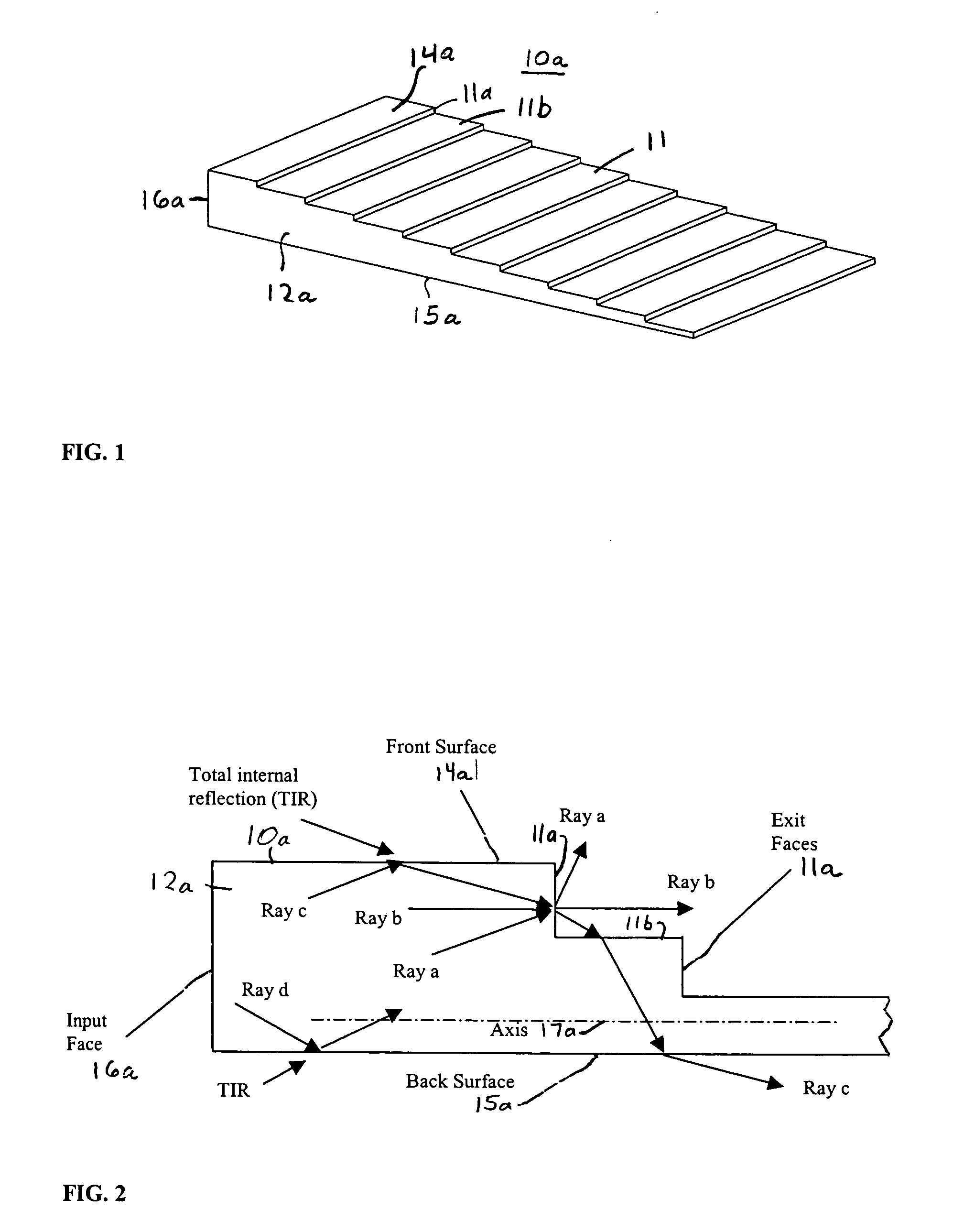
[0098]Now referring to FIG. 1, an optical device 10a of a first embodiment is shown having a body 12a of optical material with a series of steps providing a stair-case structure 11 along top surface 14a. Each of the steps is shown equally spaced. As will be shown by the theoretical discussion below, optical device 10a provides frontside output coupling, such that when light is inputted or injected into one end 16a of device 10a the light is distributed by the front exit face 11a of each of the steps, and a substantial portion of the light is internally reflected within body 12a until distributed from such front exit faces.
[0099]Optical device 10a is primarily provided to show the concept of the invention, and is considered least preferable of the embodiments described since features added to optical devices 10b-e can provide out-coupling of substantially all the light incident on a front-side while not increasing the numerical aperture of the light that does not exit the optical dev...
second embodiment
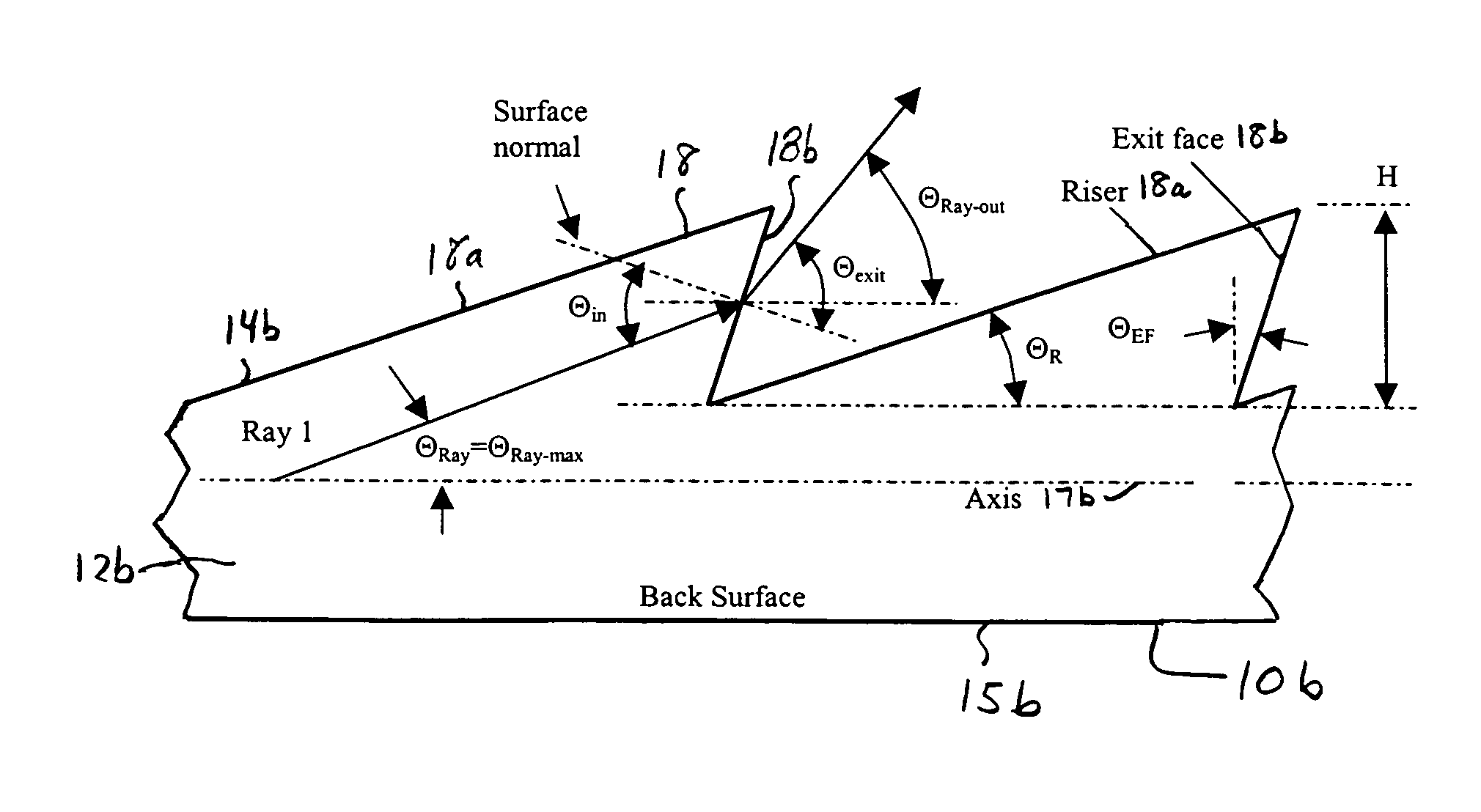
Equation (34) is the criterion for Ray 2′ to exit optical device 10c and not reenter through the subsequent riser surface 20a. If α=1 then Equation (34) reverts to the expression in Equation (17) for second embodiment optical design 10b. The solutions to this relationship are plotted in FIG. 20. As the parameter α is increased, the upper angular limit moves down, narrowing the solution space. For the case of α=1.3, the riser angle must be less than 8 degrees for an exit face angle of 20 degrees. For example, an 8 degree riser angle for α=1.3 provides an effective thickness reduction, as described in Equation (29), of about 2.4 degrees.
[0134]The design constraint imposed by the extreme reflective-refractive ray interaction on the front-face 20b for optical device 10c will now be described. For this discussion, FIG. 21 shows the Ray 4′ interactions. The height of the ray Hray at the exit face 20b is given by the expression:
HRay≅(HEF−H)+LR*tan(Θ′Ray), (35)
where once again this is an a...
fifth embodiment
[0165]Referring to FIG. 46A, optical device 10e of the present invention is shown having a structured backside surface that emits light from its top surface. Optical device 10e has a body 30 of optical material with ramp structures 32 and rising structures 36 that alternate with each other along the bottom surface 34 of the device. The ramp structures 32 and falling structures 36 extend along a dimension representing the axis 37 of the device, which is substantially parallel to the top surface 33 of the device, as best shown in FIG. 48. Each ramp structure 32 has a rising surface (or riser) 32a at an acute angle with respect to axis 37. Each falling structure has a falling surface at an acute angle with respect to the normal 37a of axis 37, and then a surface 36b substantially parallel to the top surface. The device's body gradually reduces in thickness as the ramp structures 32 alternate with the falling structures 36 extend along the device from end 38 to end 39. As will be shown ...
PUM
| Property | Measurement | Unit |
|---|---|---|
| refractive index ratio | aaaaa | aaaaa |
| refractive index ratio | aaaaa | aaaaa |
| refractive index ratio | aaaaa | aaaaa |
Abstract
Description
Claims
Application Information
 - R&D
- Intellectual Property
- Life Sciences
- Materials
- Tech Scout
- Unparalleled Data Quality
- Higher Quality Content
- 60% Fewer Hallucinations
Browse by: Latest US Patents, China's latest patents, Technical Efficacy Thesaurus, Application Domain, Technology Topic, Popular Technical Reports.
© 2025 PatSnap. All rights reserved.Legal|Privacy policy|Modern Slavery Act Transparency Statement|Sitemap|About US| Contact US: help@patsnap.com


