Do-it-yourself wind power generation wall

a wind power generation and wall technology, applied in the direction of electric generator control, rod connection, coupling, etc., can solve the problems of ozone layer depletion and greenhouse effect, practical applications of traditional wind power generation apparatus, and high overall price, so as to reduce material and installation costs, maximize the performance of a limited area, and improve the overall power generation performance per unit area

Inactive Publication Date: 2009-09-29
JETPRO TECH
View PDF66 Cites 21 Cited by
  • Summary
  • Abstract
  • Description
  • Claims
  • Application Information

AI Technical Summary

Benefits of technology

[0008]Therefore, it is a primary objective of the present invention to provide a do-it-yourself wind power generation wall composed of small standard components, so that users can freely install the power generation wall according to the environment of its application, and the invention can greatly improve the site and scope of utilizing the power generation wall.
[0010]Another objective of the present invention is to provide a do-it-yourself wind power generation wall that makes use of an alternate arrangement of upper and lower rows of wind power generation units to maximize the performance of a region of a limited area and greatly improve the overall power generation performance per unit area.
[0011]A further objective of the present invention is to provide a do-it-yourself wind power generation wall capable of effectively overcoming the difficult installation of traditional wind power generation apparatuses and reducing material and installation costs.

Problems solved by technology

As natural resources such as petroleum are extracted and used extensively, the inventory of natural resources becomes increasingly less, their price keeps on climbing, and a huge quantity of greenhouse gases such as carbon dioxide is released, and all of the above are the main causes giving rise to ozone layer depletion and greenhouse effect.
However, the practical applications of the traditional wind power generation apparatus still have the following problems.
Since the traditional wind power generation apparatus comes with a large volume and a fixed structural configuration and requires complicated circuit layout and wire connections to different conducting wires, therefore the overall price is very high.
In addition, a plurality of wind power generation units are arranged and installed at upper and lower rows correspondingly, not only wasting spaces, but also affecting the total power generation performance per unit area.
The traditional wind power generation apparatus is in a fixed structural configuration, and a large hoist is usually required for the installation, and thus traditional wind power generation apparatuses not only incur high installation fee, but also fit applications at a specific site or environment only, and all of the above reduce the practicability and economic benefits of the wind power generation apparatus.

Method used


Image

  • Do-it-yourself wind power generation wall
  • Do-it-yourself wind power generation wall
  • Do-it-yourself wind power generation wall

Examples


Embodiment Construction

[0022]The technical characteristics, features and advantages of the present invention will become apparent in the following detailed description of the preferred embodiments with reference to the accompanying drawings. The drawings are provided for reference and illustration only, but not intended for limiting the present invention.

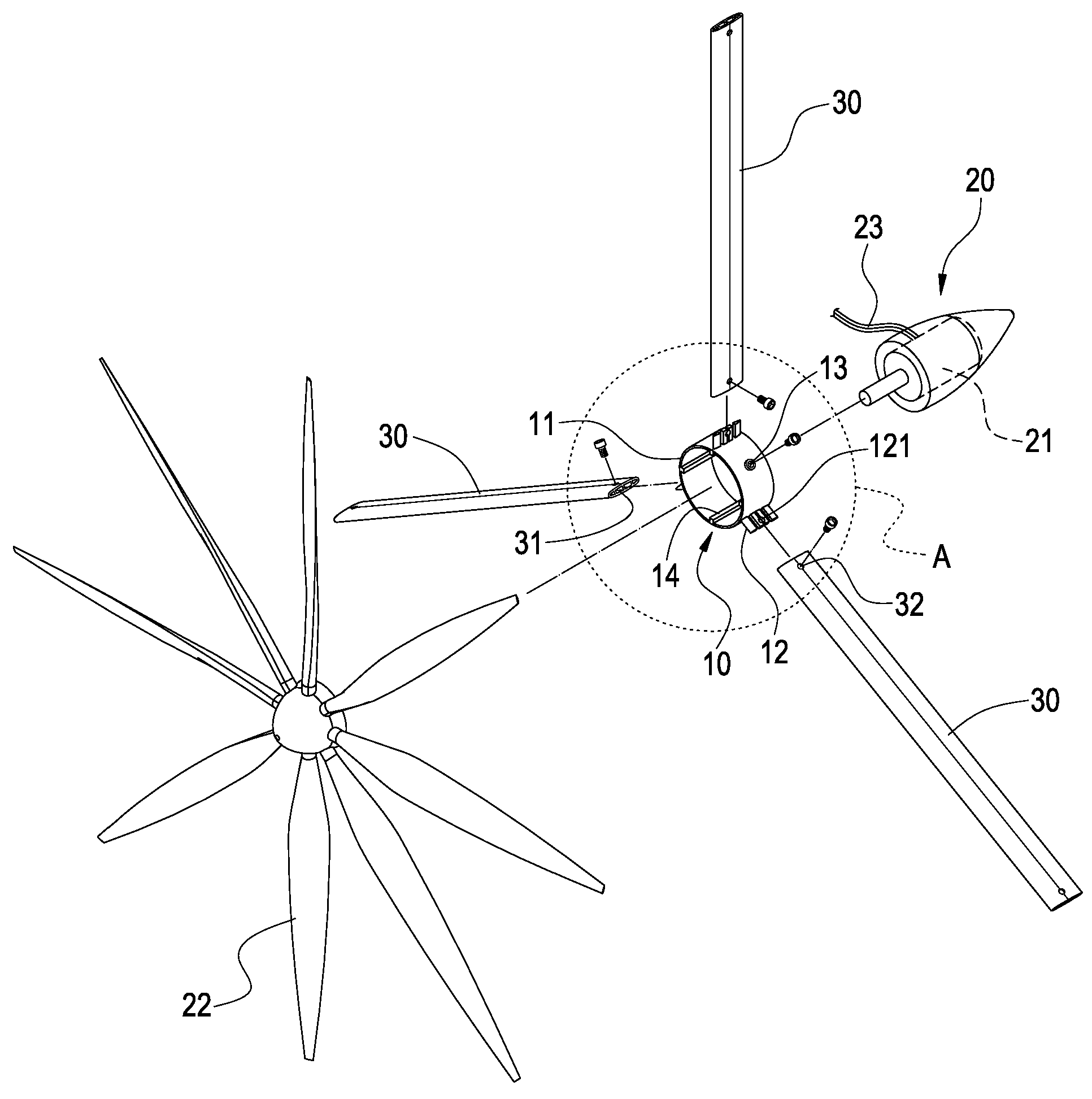
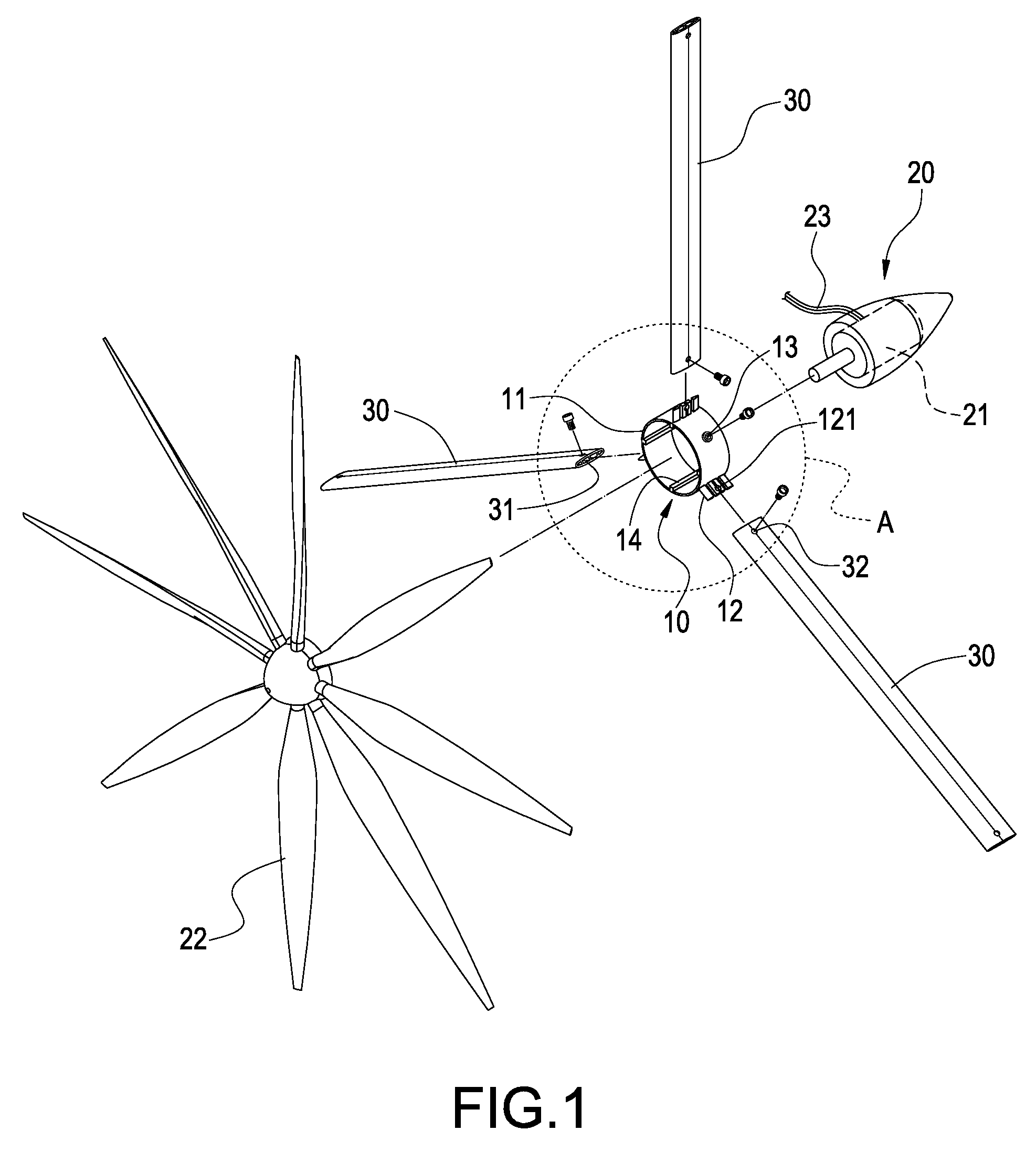
[0023]Referring to FIGS. 1 to 3 for an exploded view of some elements of the invention, an enlarged view of Section A of FIG. 1 and a schematic view in accordance with the present invention respectively, the present invention provides a do-it-yourself wind power generation wall formed by a plurality of wind power generation modules, and the wind power generation module of this preferred embodiment comprises a bushing 10, a wind power generation unit 20 and a plurality of connecting rods 30.

[0024]The bushing 10 is a cylindrical body 11 including: a plurality of insert portions 12 disposed at the external periphery of the cylindrical body 11, and each being...


PUM


Abstract

A do-it-yourself wind power generation wall includes a plurality of wind power generation modules, each having a bushing, a wind power generation unit and a connecting rod. The exterior of the bushing forms a plurality of insert portions, and the wind power generation unit includes an electric generator connected to the bushing, and a vane wheel connected to the electric generator and formed on a side of the bushing, and an end of the connecting rod is sheathed onto an insert portion of the bushing, and each wind power generation module is connected to form a power generation wall. The invention allows users to freely install the power generation wall according to the environment of the application and greatly enhances the site and scope of using the power generation wall.

Description

BACKGROUND OF THE INVENTION[0001]1. Field of the Invention[0002]The present invention relates to an electric power generation apparatus, and more particular to a wind power generation wall applied to a roof or between windows.[0003]2. Description of Prior Art[0004]As natural resources such as petroleum are extracted and used extensively, the inventory of natural resources becomes increasingly less, their price keeps on climbing, and a huge quantity of greenhouse gases such as carbon dioxide is released, and all of the above are the main causes giving rise to ozone layer depletion and greenhouse effect. Thus, solutions for a substitute of electric power generation such as solar power generation, wind power generation and hydropower generation are provided, and these power generations have become an important subject for manufacturers of the related industry.[0005]A traditional wind power generation apparatus as disclosed in R.O.C. Utility Model No. M250048 includes: a base; a frame e...

Claims


Application Information

Patent Timeline
Patent Type & Authority Patents(United States)
IPC IPC(8): H02P9/04F03D9/00F16D3/00E04G7/00F16B12/36F16B7/00F16B7/04F16D1/00
CPCF03D1/00F05B2240/40F05B2240/9112Y02B10/30Y02E10/725Y10T403/44Y10T403/10Y10T403/553Y10T403/30Y10T403/345Y02E10/728Y02E10/72
Inventor CHEN, SHIH HLI, KA-SHING
Owner JETPRO TECH
Why Eureka
Try Eureka