
RFID tag and RFID system having the same

a technology of rfid which is applied in the field of radio frequency identification (rfid) reader and rfid tag having the same, can solve the problems of increased reflection signal, increased power loss of rfid reader, and high coefficient between rfid reader and rfid tag, so as to achieve stably modulation and demodulation, and enhance product reliability

Inactive Publication Date: 2009-09-29
SAMSUNG ELECTRONICS CO LTD
View PDF9 Cites 18 Cited by
  • Summary
  • Abstract
  • Description
  • Claims
  • Application Information

AI Technical Summary

Benefits of technology

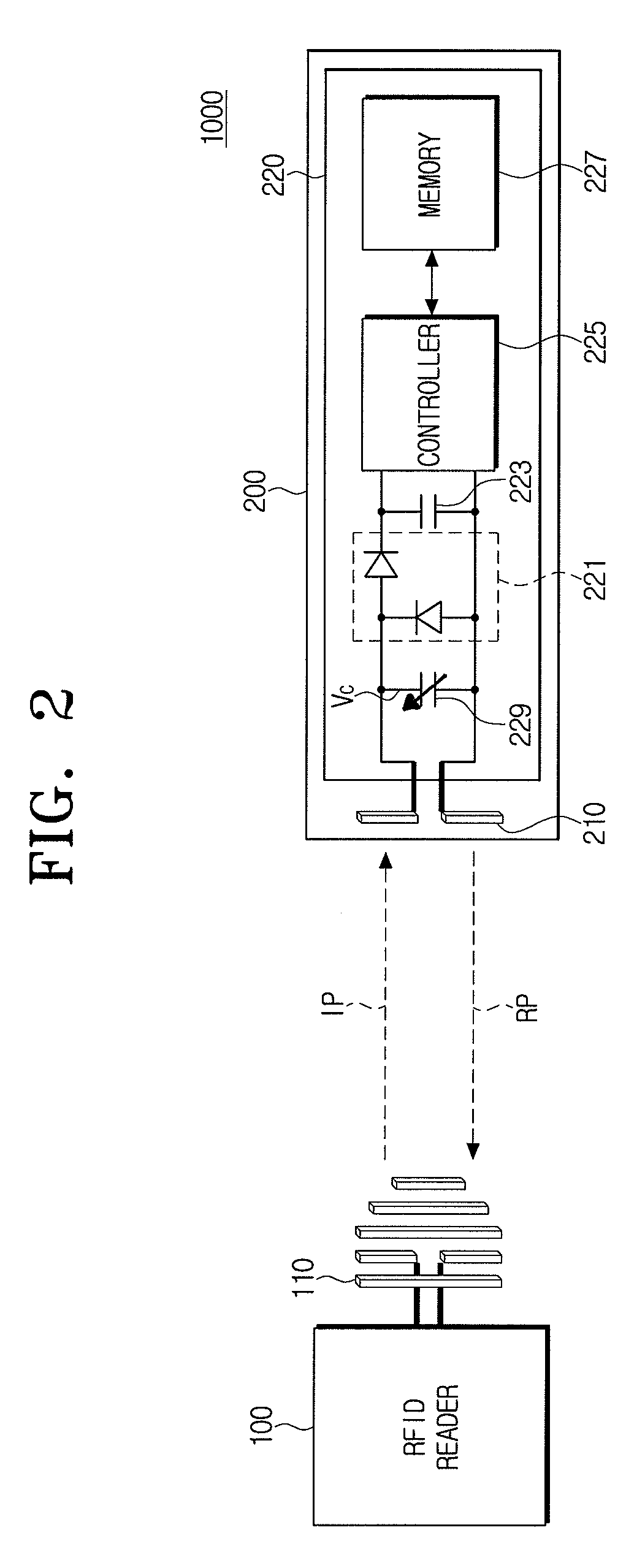
The present invention provides an RFID tag with improved reliability by stably adjusting the voltage on transmission of a carrier wave. The RFID tag includes a tag antenna and a tag driver with an accumulation mode capacitor that adjusts impedance for stable modulation and demodulation. The accumulation mode capacitor can adjust its capacitance value based on the intensity of the reflection power, which is generated by modulating the carrier wave. This allows the RFID tag to prevent the voltage transmitted from the tag driver from being lower than the reference voltage, ensuring stable modulation and demodulation. The RFID system includes an RFID reader and the RFID tag, enhancing the reliability of products.

Problems solved by technology

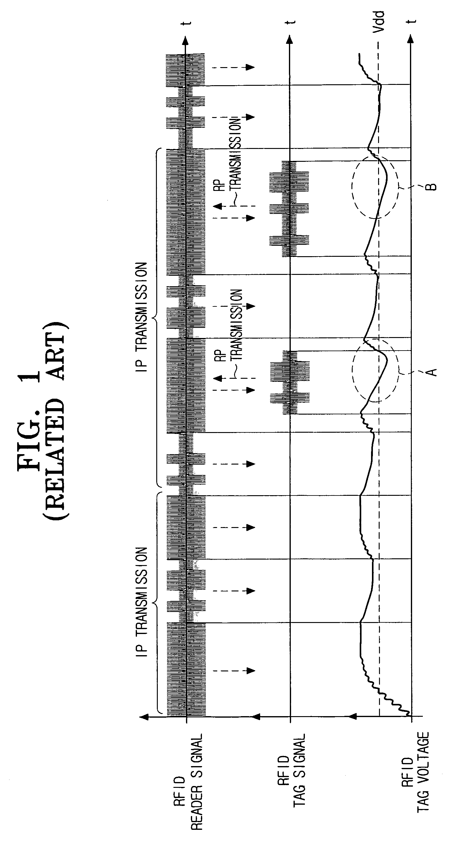
That is, if impedance matching between the RFID reader and the RFID tag is not accurately performed, a reflection coefficient between the RFID reader and the RFID tag become high and the reflection signals increase so that power loss of the RFID reader increases.
As described above, as the variation of voltage transmitted from the driving chip increases according to the amplitude variation of a data signal in the RFID tag, circuits embedded in the RFID tag can unstably drive.
Accordingly, the power supply of the RFID tag is unstable, and modulation and demodulation are unstable, so that signal transmission / reception between the RFID reader and the RFID tag cannot be normally performed.

Method used


Image

  • RFID tag and RFID system having the same
  • RFID tag and RFID system having the same
  • RFID tag and RFID system having the same

Examples


Embodiment Construction

[0043]Hereinafter, exemplary embodiments of the present invention will be described in detail with reference to the accompanying drawing figures.

[0044]In the following description, same drawing reference numerals are used for the same elements even in different drawings. The matters defined in the description such as a detailed construction and elements are nothing but the ones provided to assist in a comprehensive understanding of the invention. Thus, it is apparent that the present invention can be carried out without those defined matters. Also, well-known functions or constructions are not described in detail since they would obscure the invention in unnecessary detail.

[0045]FIG. 2 is a schematic diagram illustrating an RFID system according to an exemplary embodiment of the present invention.

[0046]Referring to FIG. 2, the RFID system 1000 according to an exemplary embodiment of the present invention includes an RFID reader 100 and an RFID tag 200.

[0047]More specifically, the RF...


PUM


Abstract

An RFID tag capable of enhancing the reliability of products and an RFID system having the same are provided. The RFID tag includes a tag antenna receiving waves from an RFID reader, and a tag driver. The tag driver includes an accumulation mode capacitor adjusting a capacitance value corresponding to an input voltage. That is, the tag driver adjusts the amplitude of a modulated carrier wave using the accumulation mode capacitor. Accordingly, the RFID tag adjusts the impedance of the tag driver without adjusting the current transmitted from the tag driver. Therefore, impedance adjustment of the tag driver can prevent the voltage transmitted from the tag driver from being lower than the reference voltage, and modulation and demodulation can be stably performed. As a result, the reliability of products can be enhanced.

Description

CROSS-REFERENCE TO RELATED APPLICATIONS[0001]This application claims priority from Korean Patent Application No. 10-2006-0006463, filed Jan. 20, 2006 in the Korean Intellectual Property Office, the entire contents of which are incorporated herein by reference.BACKGROUND OF THE INVENTION[0002]1. Field of the invention[0003]The present invention relates to a radio frequency identification (RFID) tag and an RFID system having the same. More particularly, the present invention relates to an RFID tag to stably control impedance on transmitting a carrier wave and an RFID system having the same.[0004]2. Description of the Related Art[0005]RFID is an automatic recognition technology using wireless frequencies and is a representative new technology of a contactless integrated circuit (IC) card to replace a barcode and a magnetic card.[0006]The RFID system includes an RFID reader, a host computer and a transponder, that is, an RFID tag.[0007]The RFID reader transmits radio waves to the RFID t...

Claims


Application Information

Patent Timeline
Patent Type & Authority Patents(United States)
IPC IPC(8): G08B13/14H04B5/00H04Q5/22H04B5/48
CPCG06K19/0723H01L29/94H01L29/93H01L27/0727E05B49/00G07C9/00563G07C2009/00976
Inventor KU, JA-NAMLEE, SEONG-HEARNLEE, DONG-HYUN
Owner SAMSUNG ELECTRONICS CO LTD
Learn More